6 Implementation
The implementation will be done in the phased manner, in the direction from the functions in the concept to its implementation on the Qt library, and so on until the last component. Such an approach allow to get results between stages, analyze it and take into minds the peculiarities in the following stages. For step by step implementation lets divide the whole problem into logical parts and put them depending of one another in the implementation.
6.1 Widgets and Libraries
The objectives of this phase are:
- Implementation of the basis of the architecture "Data model" — "Visualization" in the face of the modules of OpenSCADA system: "UI.VCAEngine" — "UI.Vision".
- Implementation of the basic functions of the data model of VCA in the module UI.VCAEngine:
- Organization of the storage of the model data of the module UI.VCAEngine in the databases available in OpenSCADA.
- Writing scenarios of the data model control of the UI.VCAEngine module by means of the control interface of OpenSCADA.
- Creating an abstract class of widget VCA::Widget.
- Creating a class of widgets library VCA::WdgLib.
- Creating representative classes of the library VCA::LWidget and container VCA::CWidget widget.
- Creating a representative class of the terminal widget VCA::PrWidget (the end visualization element).
- Creating a primary version of the library of the terminal widget, data model of the visualization primitives.
- Implementation of the basic functions of development framework of user interface in the visualization module UI.Vision:
- Building the basis of the user interface of developing on the Qt library.
- Forming a navigator through the libraries of widgets and tools for their management.
- Forming an inspector of the widget's attributes.
- Forming a dialogue of the editing the properties of the library.
- Forming a dialogue of the editing widget's properties.
- Forming a graphical editor of the frames and the basis of the graphic editing of the final visualization elements (primitives).
As the result of our work the modules of the data model UI.VCAEngine and visualization UI.Vision were created. At this stage, the modules implement mechanisms of UI elements forming. At next stage these elements will be used to form the full-fledged visualization and control interfaces.
Lets consider the results of the stage's implementation by the points:
Implementation of the basis of the architecture "Data model" - "Presentation(visualization)"
According to the static class diagram (Fig.4.11.1) and general requirements there have been implemented the modules "UI.VCAEngine" and "UI.Vision" for the OpenSCADA system. The "UI.VCAEngine" module implements the VCA data model and is the source for subsequent presentation of these data by different mechanisms of visualization. The "UI.Vision" module provides the method of presentation(visualization), based on Qt library of version 4 of the ![]() Trolltech company.
Trolltech company.
Relation between the modules of the data model and presentation(visualization) is organized by direct calls (strong links). This method is selected for preliminary abstraction of features of interaction and for concentration on core problems of implementation. Later it is planned the unification and construction of these links through the control interface of OpenSCADA system (weak links). As the result it will be achieved the opportunity of separation the data model and presentation(visualization), with possibility of simultaneous maintenance of different presentation(visualization) mechanisms with the single VCA data model. In addition, it will be possible to estimate the influence of the connection's(link's) type on performance of the VCA.
Implementation of the basic functions of the VCA data model in the UI.VCAEngine module
A module of the data model(engine) of the VCA contains the container of widgets/frames library. The module provides a predefined library of the basic widgets (primitives) with primary realization of their own properties and processing logic of these properties.
Storing of the widgets' data and widgets' libraries is implemented in a database available in the OpenSCADA system. The database is organized by the data ownership to the library. I.e separate library stores in the separate group of tables of the one or different databases. List of the libraries of the widgets stores in an index table of the libraries with the name "VCALibs" and with the structure "Libs". A copy of this table creates in each database, which stored data of this module, with the list of libraries contained in the given database. Structure of the tables of the belonging to the library widgets includes:
- {DB_TBL} — Table of widgets belonging to the library, structure "LibWigets".
- {DB_TBL}_io — Table with working properties of the widgets in this library and the embedded widgets of the container widgets, structure "LibWidgetIO".
- {DB_TBL}_uio — Table with user's properties of the widgets of this library and the embedded widgets of the container widgets, structure "LibWidgetUserIO".
- {DB_TBL}_incl — Table with the list of embedded widgets in the widgets-containers of the library, structure "LibWidgetIncl".
- {DB_TBL}_mime — Table with resources of the library and its widgets, structure "LibWidgetMime".
To control the widget library and the individual widgets the configuration scripts were written on the language of control interface of ~OpenSCADA. Currently, these scripts are designed to perform only the functions of the central configuration of the VCA engine elements, but later there is plans to expand them and give them the functions of processing requests to the data model from the presentation(visualization) modules to organize the "weak links" between the "Data model" and "Presentation (visualization)".
Basis of practical all elements of the engine has become an object of the abstract visualization element VCA::Widget. At its, abstract, level the object has the following properties:
- "Using" inheritance — the mechanism of inheritance of individual properties of another instance of the object. It is used for organizing the mechanism of secondary using, redefinition and completion of the elements of visualization.
- Storage the properties(attributes) of widgets with the mechanisms of "using" inheritance of the values. The mechanism of "using" inheritance does the inheritance of the properties' values from the root element and to the top one, with the ability to redefine the values at each level. In this case, the database stores only the values of modified properties.
- Support of the container mode. In this mode, the widget may include other(child) widgets, like the widget library contains of widgets. It is used in library widgets that inherit properties of the primitive-container, such as the frame primitive "Box". Also, this property will be used in the session of the project to build the hierarchical tree of widgets(primitives) in the formation of the final image of frames' visualization.
- Support of a mode of simple connection. This mode is used for the embedded widgets of the library. The feature of this mode is that it does not inherit the properties of the container, and therefore can not directly contain the embedded widgets (Part 4.5).
- Contains the procedure of the internal logic of the widget on one of the languages of the OpenSCADA system. The logic of this procedure can be used to organize the interaction of embedded widgets and container with each other to form the desired behavior.
- Providing of access to the resources, mime-data, taking into account the hierarchy of "using" inheritance.
For presentation of the library of widgets the class VCA::WdgLib is implemented. Its main functions are to maintain the library of widgets, storage and loading them from the database, providing an access to the resources(Mime-data), as well as the access control.
Especially for including into the library of widgets a class of the library widget VCA::LWidget was created, which is based on an abstract widget's class VCA::Widget and provides additional functions: storing the widget's data in tables of the library, redefinition of the access to the resources on the table with the mime-data of the library and storage of the included container widget VCA::CWidget.
In its turn, the class of the container widget VCA::CWidget provides the following functions: storing of the container widget's data in tables of the library, redefinition of the access to the resources on the table with the mime-data of the library and the forced mode of the simple link for all container widgets.
Based on the library widget's class VCA::LWidget it was formed an abstract class of terminal widget VCA::PrWidget. And based on its implementations of primitives of basic widgets are formed, which form the library of basic widgets, which are created by the module at the initialization. Values of the properties of the basic widgets, also can be stored in the database (tables of the widget's library), forming the desired templates. In addition, the basic library of primitives can redefined by the extended primitives from the modules of the presentation(visualization) interfaces, for which the basic ones are not enough. But in this case it must be taken into account that such action — the way to an incompatibility between the modules of the presentation(visualization) interfaces!
Implementation of basic functions of the development framework of the user interface in the presentation(visualization) module UI.Vision
Framework of the user interfaces' development of the module based on MDI (Multi Document Interface) interface. This approach allows you to simultaneously edit multiple frames of various sizes. Following arrangements for managing the development are used: the toolbar, menu and context menu. Most actions are duplicated in the different mechanisms, so you can quickly find the tool by the preferred method. Navigation interfaces are implemented by the attachable windows. The configuration of toolbars and attachable windows are saved on exit and restored at startup that lets you to configure the interface for yourself.
One of the elements of the user interface, implemented as the attachable window is a browser of the widget's library. With the browser you can quickly find the widget or the library and do the necessary operations on them. The following operations are implemented: addition, deleting, configuration of widgets and libraries, as well as visual editing of the widget.
For easy management of the properties of widgets/frames the inspector of attributes(properties) of widgets is implemented. Inspector of the attributes is implemented as the attachable window, which is activated when you select the frame or widget. Window of the inspector of attributes can be conveniently positioned by attaching it to one of sides of the working window. Inspector of attributes supports the group configuration of several widgets, as well as grouping of similar properties.
For visual editing of the frames the primary support for editing of widgets and frames is implemented. Even now the editor allow you to edit the frames, based on the primitive Box, and the text field primitive "Text" full-featured display. In the editor the following functions are implemented:
- selection of a widget and a group of widgets on the frame;
- moving of widgets through the frame;
- resizing selected widgets on the frame;
- editing properties of the selected widgets;
- alignment and management of levels of visualization of the selected widgets.
Development window is shown in Fig. 6.1.1, where you can see: the toolbar, navigator of widgets, inspector of attributes, editing window of the frame and status bar.
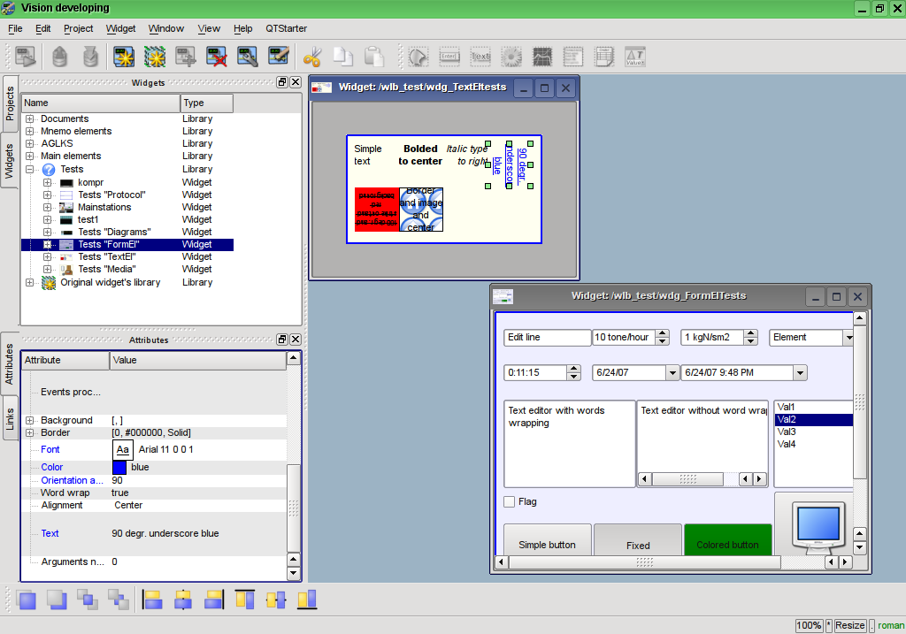
Fig.6.1.1 Development window of the UI.Vision module
To configure the widgets' objects and their libraries two dialogues are implemented: the dialogue of the widget's configuration (Fig.6.1.2) and the configuration dialog of the widget's library configuration (Fig.6.1.3). The library configuration dialog allows you to set the basic properties of the library and put the mime-data in the database for subsequent using in the widgets of the library. Widget's configuration dialog allows you to set: basic properties of the widget, individually to set the values of attributes and configure the internal procedure for computing the widget with additional(user's) properties.
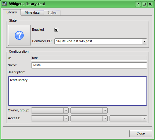
Fig.6.1.2 Dialog of the widget's library configuration.
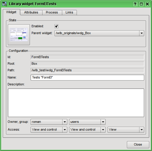
Fig.6.1.3 Dialog of the widget's configuration.
6.2 Visualization interface projects
Objectives of this stage are:
- Projects of the visualization interfaces implementations at level of the VCA data model in the UI.VCAEngine module:
- Link tools development of the frame: local links inside the frames, external links to parameters of the data acquisition subsystem of OpenSCADA and actions of the interface to events.
- Pages' tree of the project and their relations development.
- Projects of the visualization interfaces implementation in the presentation(visualization) module UI.Vision(Qt):
- Navigator on the projects forming.
- Configuration dialog of a project's page forming;
- Implementing of support for possibility of direct graphical forming of a page on the project's level with possibility of the visual linkage (including the logic links).
At this stage, it was added the mechanism of VCA projects formation by means of the building of the visualization pages in hierarchical form, which corresponds to logical links in the final VCA interface. During the implementation of this stage, the work was begun on adaptation of the visualization module "Vision" to use the control interface of OpenSCADA instead of direct-strong links. These works have led to significant unification of the various dialogues, control structures and user interface in general.
At this stage implemented:
- Links mechanism. Just on the parameters of data sources! Internal links will be implemented in subsequent stages.
- Inspector of links of the module "Vision", using scenarios of the control interface of OpenSCADA.
- Mechanism of formation of the pages' tree based on the terms: page-template and page-container. This mechanism allow you to simply describe the relationship between the pages of most known types of user interface with an effective addressing and links to pages either individually or by template.
- Navigator through the project's tree, as on the scripting language of control interface and in the module "Vision", using the same scenarios of the control interface.
- Dialogue of the project's and the project page's configuration. In fact, the configuration dialogs of the project's and the library's elements are combined and also transfer to weak links of the control interface of OpenSCADA is done.
- Thanks to the unification of the interface of access to the elements of the library and the project, possibility of direct formation of pages on project's level is implemented.
6.3 Sessions of the project's running
Objectives of this stage is:
- Implementation of execution sessions of the projects at level of the VCA data model in the UI.VCAEngine module:
- Forming of hierarchical tree of widgets of the final visualization based on the project for which the session opens.
- Forming of values' frames for the procedures of final visualization widgets' calculation.
- Processing links on parameters of the data sources of OpenSCADA.
- Implementation of hierarchical calculation of the procedures and updating the widgets links.
- Forming of mechanism of transmission and processing of events in the hierarchical tree.
- Implementation of visualization of the projects' sessions in the visualization module UI.Vision (Qt) as a full featured user interface with elements of visualization of dynamics, history and control:
- Forming of execution window of the project (Runtime).
- Visualization of the project's frames in the "Runtime" mode with periodic update of the content.
- Implementation of transmission and processing of the events.
- Implementation of mechanism of switching/opening/substitution/navigation through the pages of the project taking into account the scenarios(scripts) of processing.
At this stage it was added mechanism of the project's execution in the sessions of the data model of the VCAEngine module, as well as visualization of the project's session, the "Runtime mode in the visualization module on the Qt library Vision with the elements of the data update and interaction with the user.
Forming of hierarchical final visualization widgets' tree based on the project for which the session is opened.
According to Fig.4.11.1 and Part 4.5 objects of the project's session are inherited from abstract object Widget and use appropriate objects of the project. Thus, the session Session uses the project Project and forms the expanded tree on basis of it. Project's page Page is directly used by the session's page SessPage. Remaining objects (SessWdg) are unwrapped in accordance with hierarchy of the page's elements (Part 4.5).
In addition to standard properties of the abstract widget Widget the elements of the page and pages of session get the properties of storage of frame of values of the computational procedure, calculation of procedures and events' processing mechanism. Pages of the session, in addition to all, contain the container of following by the hierarchy pages. The session is calculated with the specified periodicity and in the following sequence:
- "Top level page" -> "Lower level page "
- "Lower level widget" -> "Top level widget"
This policy allows you to pass pages according to the hierarchy, and events in the widgets to rise to the top in one iteration.
Session implements support for the special properties of the pages:
Template — page is template for the underlying pages;
Empty — blank inactive page, this property is used in conjunction with the property Container for logical containers organization.
Based on the properties the following types of pages are implemented:
Container — full-featured page with the container property (Container).
Logical container — logical container which is actually not a page (Container|Empty). It performs the function of intermediate and grouping element in the pages tree.
Template — template page (Template). Pure template page which is used to describe common properties and for extending them privately in the embedded pages.
Container and template — Template and container page (Template|Container). It combines the template and the container functions.
Forming values' frames for the final visualization widgets' calculation procedures.
In the section above, we have already noted that widget of the session contains frame of values of the calculation procedures. This frame is initiated and is used in case of presence of the calculation procedure. During initialization of list of parameters the procedure is created and compilation of the procedures with these parameters is done in the module that implements the selected programming language and that id encoded with the full name of the widget. The compiled function is connected to the frame of values of calculation procedures. Next, the calculation is done with the periodicity of the session.
Calculation and processing of the widget as a whole is done in the following order:
- events, available at the time of calculation, are selected from the attribute "event" of the widget;
- events are loaded into the parameter "event" of the calculation frame;
- values of input links are loaded into the frame of calculation;
- values of special variables are loaded in the calculation frame (f_frq, f_start and f_stop);
- values of selected parameters of the widget are loaded into the calculation frame;
- calculation;
- upload of the calculation frame's values to the selected parameters of the widget;
- upload of the calculation frame's values on the outgoing links;
- upload of the events from the parameter "event" of the calculation frame;
- process the events and transfer the not processed ones to a higher level.
Links on the data sources of OpenSCADA processing.
At execution of a widget of the session it is necessary to make the links' processing. At the moment the connection on the links is made at the time of calculation, which is not a quick operation. Implementation of the links processing will be reviewed and optimized in the future.
Support for the following types of links is provided:
- Constant value ("V"). The variable to determine at the time of configuration on the page in the project.
- Attribute of parameter of subsystem "Data acquisition" ("P"). The mechanism of access to values of the parameter of subsystem "Data acquisition" of the OpenSCADA system.
- Attribute of the embedded widget ("W"). Internal direct link between the embedded widgets.
Forming window of the project execution (Runtime).
On side of visualization (Vision module) to visualize the process of execution of the project the VisRun object is implemented. At startup it sends a request to create and initialize the session. Next a request on list of opened pages is made. Based on the information of the VisRun opened pages and their relations, the resulting interface is formed. Fig. 6.3 shows an example of classical SCADA interface with alarm objects, where the main window contains a page inside which is replaced by pressing the buttons of alarm objects and paging.
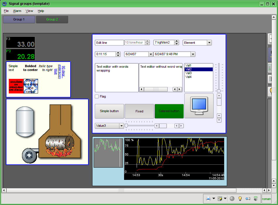
Fig.6.3 Visualization of the project's running window. The "Runtime" mode.
Visualization of the project's frames in the "Runtime" mode with periodic updating of the content.
Updating contents of the opened pages of the visualization interface with periodicity of the project's session running is implemented. In the update process it is done:
- request of list of opened pages in the model and checking consistency of the really opened pages to this list;
- requests of modified data on each page and the widget;
- updating content of the pages and their widgets in accordance with the received modified data.
By closing the "Runtime" window the closing of the project's session in the data model is made. It will be implemented the possibility to connect to the earlier opened session and disconnect from the session without closing it.
The mechanism of request of the only modified data is based on absolute counter of the session's execution. When you make real changes in the attributes of widgets the remembering of the value of this counter is made, which allows us to identify the modified attributes. This approach allows to increase productivity and reduce the load on the traffic in case of access to the model through the network.
Realization of transfer and processing of the events.
Visualizer of the ("Runtime") session, because of its direct contact with the user, collects various events. Part of the events are processed by the shapes of the basic widgets (Text, Box, Document, etc.), which can form other events. Another part is directly transfered to the data model, where they are processed.
To the data model events are transferred immediately upon their reception, where they are collected in the attribute "event" of the widget until the next iteration of the session's execution. Further, in the process of data session's calculation, the events are extracted from the "event" attribute and are processed in the procedure of the widget or in accordance with the script(scenario) in the "evProc" attribute. The events which are not processed rise to the higher widget of the model.
Implementation of the mechanism of the switching/opening/replacement/navigation through the pages of the project taking into account the processing scenarios(scripts).
Switching, opening, replacement and navigation through the pages is based on processing the events on the scenario(script) in the attribute of the active widget "evProc". Script of this attribute is written in the form of the list of commands with the syntax: {event}:{srcWdg}:{com}:{prm}, see the details into part 4.7 and part 4.4.
6.4 Designing and implementing the visualization primitives
At this stage it is planned to implement the data models UI.VCAEngine and shapes of the Vision visualizer Vision, WebVision for all the basic elements: "ElFigure", "FormEl", "Text", "Media", "Diagram", "Protocol", "Document", "Function", "Box", "Link".
6.4.1 Elementary figure primitive (ElFigure)
The implementation on the data-model side (UI.VCAEngine) describes into the document's part 4.12.
UI.Vision
Support of the following elementary figures is provided: lines, elliptical arcs, Bézier curves and fill of the closed circuit with the color and/or image. For the elementary figures the following operations are provided:
- creation/deleting of the figures;
- copying of the figure(s);
- moving and resizing of the figures by mouse and keyboard;
- possibility to connect the elementary figures to each other, getting more complex figures, for which all the properties of the source elementary figures are available;
- possibility of simultaneous movement of several figures;
- fill of the closed circuit with the color and/or image;
- generation of mouse key events at the time of the mouse-click on the filled spaces;
- scaling;
- rotation;
- mirroring, partial.
Figure shows a part of the screen with a frame containing the elementary figures.
The figures underlying this widget, containing the points (the start and end ones) that can be connected with the according points of other figures; and the points with the help of which the geometry of the figure can be changed.
It is possible to add the figure using the mouse:
- Select the desired figure from the context menu.
- Set with the left mouse-button start and end points (for line with the SHIFT key hold its orthogonal drawing is made).
The deleting of the figure(s) it is possible by pressing "Del", having selected figure(s).
The copying of the figure(s) it is possible by pressing keys "Ctrl"+"C", having selected figure(s).
Moving/resizing of the figure it is possible by using the mouse or keyboard:
- Select the figure, by clicking on it with the left mouse button.
- Drag (with the help of mouse or control keys) the figure or one of its control points in the desired location and release the mouse button (key).
It is possible to move several figures, selected by means of holding "Ctrl" and clicking on the desired figures (this option works when the button Connections (Connections) is disabled) or by mouse selection.
The connection of the figures with each other it is possible by the following way:
- Press the Connections button.
- Select one of the figures and move its start or end point to the desired start or end point of the other figure so that it will get to the appeared circle, release the left mouse button. Connected figures are moving as well as the individual, the general point is moved for all connected figures, to which it refers(priority is given to the arc, two arcs can't be connected directly with each other ).
To fill the closed circuit from the figures it is possible with the following way:
- Press the Connections button.
- Create the closed circuit.
- Make the double-click of the left mouse button inside of it.
To delete the fill of the closed circuit it is possible from the context menu of the widget; by braking the closed circuit or by double-click of the left mouse button on the already existing filled space.
Rotation of the figure is made around the center of the widget.
UI.WebVision
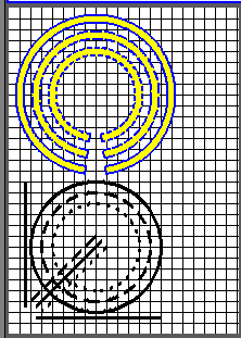
Support of the elementary figures is implemented: lines, elliptical arcs, Bézier curves and fill of the enclosed space with the color and/or image with the properties:
- Arbitrary images forming from the three elementary figures and filling of closed areas by color or image.
- There is possibility of determination of the figures' properties both in general and individual to each one: line width, color and style, line border's width and color, filling's color and image.
- Arbitrary rotation of the generic figure about its center.
- User's attributes support for dynamic points, widths, colors, styles and images.
- Events forming by mouse manipulator doings into closed areas and in generic.
Figure shows a part of the screen with a frame containing the elementary figures.
6.4.2 Primitive of the form element (FormEl)
The implementation on the data-model side (UI.VCAEngine) describes into the document's part 4.12.
UI.Vision
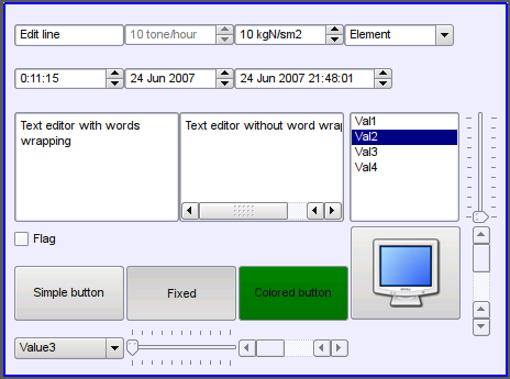
Support of the form elements on the VCA frames is provided. The following form elements are included:
- Line edit — It is represented by the following types: "Text", "Combo", "Integer", "Real", "Time", "Date", "Date and time". All kinds of line editor support the confirmation of entry.
- Text edit — It is the flat-text editor with the confirmation or denial of entry.
- Check box — Provides a field of binary flag.
- Button — Provides the button with the support of: the color of the button, the image of the button, and mode of fixation.
- Combo box — Provides the selection field of the element from the list of the items.
- List — Provides the list box with the control of the current element.
- Tree — Provides the tree element with possibility of an item selection.
- Òàáëèöà — Provides the table element with possibility of a cell, a row or a column selection and a cell content edition.
- Slider — Slider element.
- Scroll bar — Strip of the scroll bar.
The following modes are realized: «Enable» and «Active», as well as transfer of changes and events to the data model of the VCA (engine).
Figure represents a part of the screen with the frame containing the above-listed elements of the form.
UI.WebVision
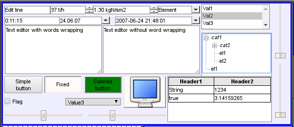
Support of the form elements on the VCA frames is provided. The following form elements are included:
- Line edit — It is represented by the following types: "Text", "Combo", "Integer", "Real", "Time", "Date", "Date and time". All kinds of line editor support the confirmation of entry.
- Text edit — It is the flat-text editor with the confirmation or denial of entry.
- Check box — Provides a field of binary flag.
- Button — Provides the button with the support of: the color of the button, the image of the button, and mode of fixation.
- Combo box — Provides the selection field of the element from the list of the items.
- List — Provides the list box with the control of the current element.
- Tree — Provides the tree element with possibility of an item selection.
- Òàáëèöà — Provides the table element with possibility of a cell, a row or a column selection and a cell content edition.
- Slider — Slider element.
- Scroll bar — Strip of the scroll bar (Equal to Slider).
The following modes are realized: "Enabled" and "Active", as well as transfer of changes and events to the data model of the VCA (engine). For all realized representations the active mode is supported, ie elements can be used to create the forms of user input.
Figure represents a part of the screen with the frame containing the above-listed elements of the form.
6.4.3 Text primitive (Text)
The implementation on the data-model side (UI.VCAEngine) describes into the document's part 4.12.
UI.Vision
Support of the text element with the following properties is provided:
- Font with the properties: type/class of the font, size, bold, italic, strikeout and underline.
- Text color.
- Text orientation.
- Automatic word wrap.
- Alignment of the text horizontally and vertically with all options..
- Displaying the background as the color and/or image.
- Display the border around the text, with the specified color, width and style.
- Formation of the text from the attributes of different types and properties.
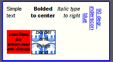
Figure 4.2 represents a part of the screen with the frame containing the text examples using various parameters.
UI.WebVision
Support of the text element with the following properties is provided:
- Font with the properties: type/class of the font, size, bold, italic, strikeout and underline.
- Text color.
- Text orientation.
- Automatic word wrap.
- Alignment of the text horizontally and vertically with all options..
- Displaying the background as the color and/or image.
- Display the border around the text, with the specified color, width and style.
- Formation of the text from the attributes of different types and properties.
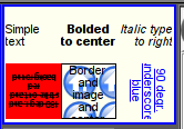
Figure represents a part of the screen with the frame containing the text examples using various parameters.
6.4.4 Primitive of the displaying the media materials (Media)
The implementation on the data-model side (UI.VCAEngine) describes into the document's part 4.12.
UI.Vision
Support of the element of the displaying of media materials with the following properties is provided:
- The indication of the source of media data (images or video material).
- View of the images of most well-known formats with the possibility of inscribing of it in the size of the widget.
- Playback of the simple animated images and video formats with the possibility to control the playback speed.
- Full format video and audio playing by
 Phonon.
- Displaying of the the background as a color and/or image.
- Display the border around the text, with the specified color, width and style.
- Formation of the active areas and generating the events when they are activated.
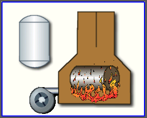
Figure represents a part of the screen with the frame containing examples of viewing/playback of media data.
UI.WebVision
Support of the element of the displaying of media materials with the following properties is provided:
- The indication of the source of media data (images or video material).
- View of the images of most well-known formats with the possibility of inscribing of it in the size of the widget.
- Playback of the simple animated images and video formats with the possibility to control the playback speed.
- Displaying of the the background as a color and/or image.
- Display the border around the text, with the specified color, width and style.
- Formation of the active areas and generating the events when they are activated.
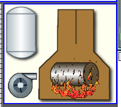
Figure represents a part of the screen with the frame containing examples of viewing/playback of media data.
6.4.5 Primitive of the construction of diagrams/graphs (Diagram)
The implementation on the data-model side (UI.VCAEngine) describes into the document's part 4.12.
UI.Vision
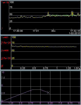
The diagrams construction element releases for types "Graph", "Spectrum" and "XY" with properties:
- General properties of the diagram types "Graph", "Spectrum" and "XY":
- possibility for select an archivator, the archive's buffer or all the data at working with archiving data;
- adapting the parameter's graph to real the data values in way the scales tune, at case the direct values range missing set;
- controlling by axis ranges in way magnification/mitigation and shifting;
- wide range scaling and adapting the time axis with automatic fitting the requested data to quality pretty for imaging, or needed for export — by set limited number measurements into pixel;
- imaging dimensional grid and markers in horizontal and vertical with adapting to the imaging range;
- tracing mode for current time by periodical update and switching the diagram time to current (time of last data into the archive buffer);
- horizontal sliding by mouse;
- scaling of a window selected part, by the mouse.
- Properties of the diagram type "Graph":
- constructing graphics up to 100 parameters into single diagram as percent scale with possibility to display self axis for selected parameters;
- constructing graph for: current, archiving and users data;
- forming intermediate displaying buffer for current only values;
- support active mode with cursor and getting the values under the cursor;
- possibility of construction graphics as into both linear, and logarithmic values scale.
- Properties of the diagram type "Spectrum":
- constructing graphics for frequency spectrum of the parameters up to 100 into single diagram as percent scale with possibility to display self axis for selected parameters;
- constructing graph for: archiving and users data;
- support active mode with cursor and getting the values under the cursor.
- Properties of the diagram type "XY":
- constructing XY graphics up to 50 parameters into single diagram as percent scale with possibility to display self axis for selected parameters;
- constructing graph for: current, archiving and users data;
- forming intermediate displaying buffer for current only values;
- the parameters distributed by pairs at one graph, where paired by axis Y (0,2,4...) and unpaired by axis X (1,3,5...);
- possibility of construction graphics as into both linear, and logarithmic values scale.
The module of visualizer provides and uses set of specific attributes of the generic means, its information are into next table. Theses attributes create by the visualizer, on its lack, at a first start.
| Id | Name | Appointment |
| sclWin | Scaling of a window selected part, by the mouse. | It is logical type attribute created by the user manually at needs. The "true" value enables the scaling of a window selected part, by the mouse. |
Figure represents a part of the screen with the frame containing examples of the diagrams: "Graph", "Spectrum" and "XY".
UI.WebVision
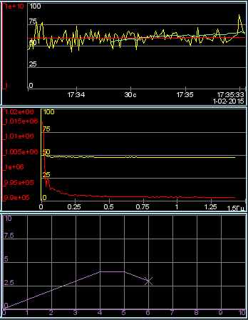
The diagrams construction element releases for types "Graph", "Spectrum" and "XY" with properties:
- General properties of the diagram types "Graph", "Spectrum" and "XY":
- possibility for select an archivator, the archive's buffer or all the data at working with archiving data;
- adapting the parameter's graph to real the data values in way the scales tune, at case the direct values range missing set;
- controlling by axis ranges in way magnification/mitigation and shifting;
- wide range scaling and adapting the time axis with automatic fitting the requested data to quality pretty for imaging, or needed for export — by set limited number measurements into pixel;
- imaging dimensional grid and markers in horizontal and vertical with adapting to the imaging range;
- tracing mode for current time by periodical update and switching the diagram time to current (time of last data into the archive buffer).
- Properties of the diagram type "Graph":
- constructing graphics up to 100 parameters into single diagram as percent scale with possibility to display self axis for selected parameters;
- constructing graph for: current, archiving and users data;
- forming intermediate displaying buffer for current only values;
- support active mode with cursor and getting the values under the cursor;
- possibility of construction graphics as into both linear, and logarithmic values scale.
- Properties of the diagram type "Spectrum":
- constructing graphics for frequency spectrum of the parameters up to 100 into single diagram as percent scale with possibility to display self axis for selected parameters;
- constructing graph for: archiving and users data;
- support active mode with cursor and getting the values under the cursor.
- Properties of the diagram type "XY":
- constructing XY graphics up to 50 parameters into single diagram as percent scale with possibility to display self axis for selected parameters;
- constructing graph for: current, archiving and users data;
- forming intermediate displaying buffer for current only values;
- the parameters distributed by pairs at one graph, where paired by axis Y (0,2,4...) and unpaired by axis X (1,3,5...);
- possibility of construction graphics as into both linear, and logarithmic values scale.
Figure represents a part of the screen with the frame containing examples of the diagrams: "Graph", "Spectrum" and "XY".
6.4.6 Primitive of the protocol formation (Protocol)
The implementation on the data-model side (UI.VCAEngine) describes into the document's part 4.12.
UI.Vision
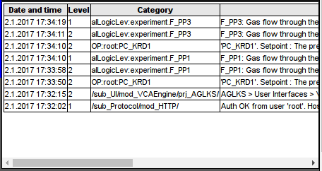
Support of the element of the formation of the protocol with the following properties is provided:
- Formation of the protocol from the archive of messages for the specified time and depth.
- Request of the data from the messages archivers.
- Selection of data from the archives by the level of importance and the category of messages template.
- Support the tracking mode for the appearance of messages in the archive of messages.
Figure represents a part of the screen with the frame containing an example of the protocol.

UI.WebVision
Support of the element of the formation of the protocol with the following properties is provided:
- Formation of the protocol from the archive of messages for the specified time and depth.
- Request of the data from the messages archives.
- Selection of data from the archives by the level of importance and the category of messages template.
- Support the tracking mode for the appearance of messages in the archive of messages.
Figure represents a part of the screen with the frame containing an example of the protocol.
6.4.7 Primitive of the protocol formation (Document)
The implementation on the data-model side (UI.VCAEngine) describes into the document's part 4.12.
UI.Vision
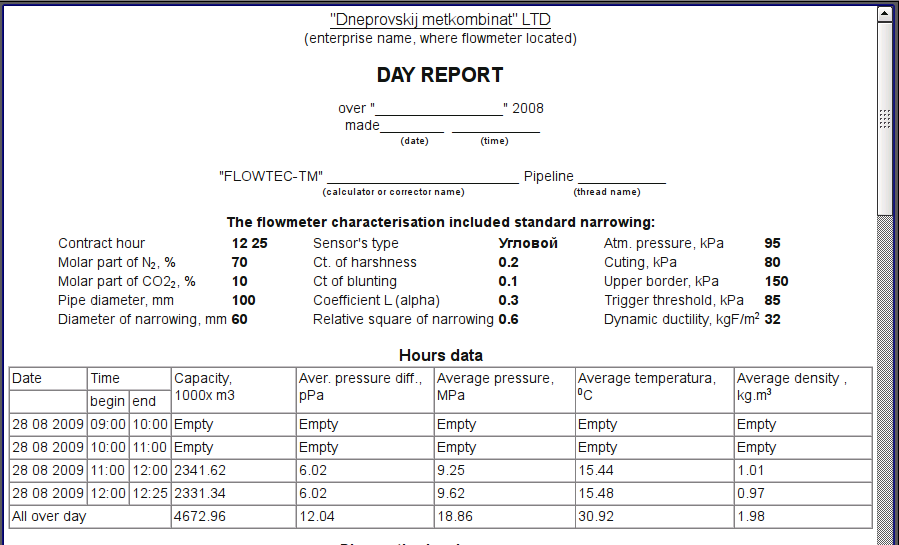
Support element of the report formation with the following properties is provided:
- Adaptive formation of a document structure based on Hypertext Markup Language. This provides support for the broad features of formatting of the documents.
- Formation of the documents on command or on schedule. It is necessary for creation of reports into the archive and then view the archive.
- Formation of a document in real time mode. It is necessary to form documents completely dynamically, and based on the archives for the specified time.
- Using of the the attributes of the widget for transmission of values and addresses to the archives in the report. It allows you to use the widget of the document as a template when generating reports with other input data.
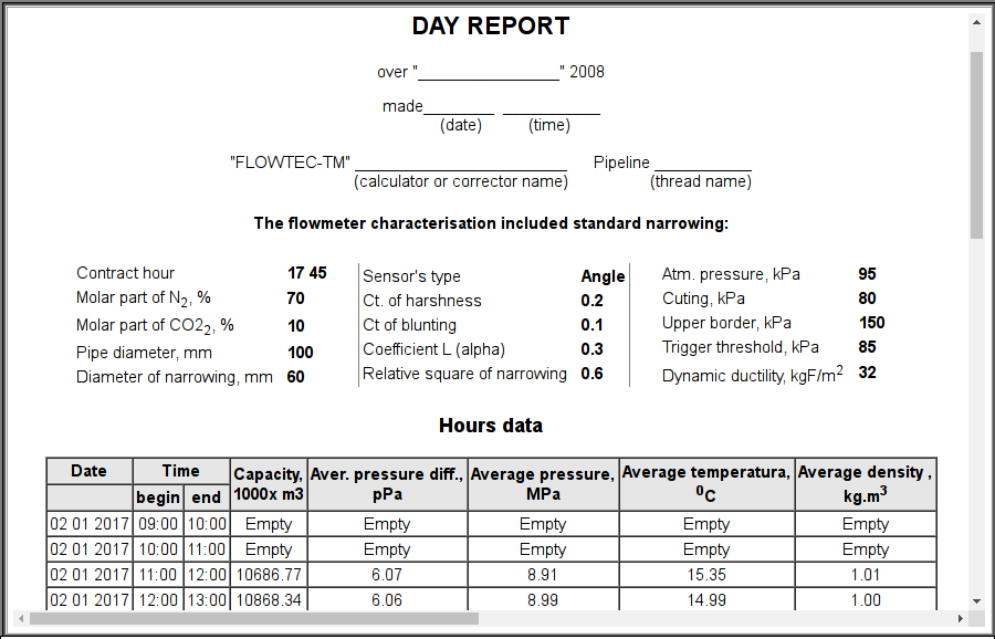
The basis of any document is XHTML-template. XHTML-template is the tag "body" of the WEB-page which contains the document's static in the standard XHTML 1.0 and elements of the executable instructions in one of the languages of the user programming of OpenSCADA in the form of <?dp {procedure} ?>. The resulting document is formed by the execution of procedures and insert of their result into the document.
The source for values of the executable instructions are the attributes of the widget of the primitive, as well as all the mechanisms of the user programming language. Attributes may be added by the user and they can be linked to the actual attributes or parameters or they can be autonomous, values of which will be formed in the script of the widget. In the case of linked attributes the values can be extracted from the history, archive.
Figure shows the frame containing a sample of the document.
UI.WebVision
Support element of the report formation with the following properties is provided:
- Adaptive formation of a document structure based on Hypertext Markup Language. This provides support for the broad features of formatting of the documents.
- Formation of the documents on command or on schedule. It is necessary for creation of reports into the archive and then view the archive.
- Formation of a document in real time mode. It is necessary to form documents completely dynamically, and based on the archives for the specified time.
- Using of the the attributes of the widget for transmission of values and addresses to the archives in the report. It allows you to use the widget of the document as a template when generating reports with other input data.
The basis of any document is XHTML-template. XHTML-template is the tag "body" of the WEB-page which contains the document's static in the standard XHTML 1.0 and elements of the executable instructions in one of the languages of the user programming of OpenSCADA in the form of <?dp {procedure} ?>. The resulting document is formed by the execution of procedures and insert of their result into the document.
The source for values of the executable instructions are the attributes of the widget of the primitive, as well as all the mechanisms of the user programming language. Attributes may be added by the user and they can be linked to the actual attributes or parameters or they can be autonomous, values of which will be formed in the script of the widget. In the case of linked attributes the values can be extracted from the history, archive.
Figure shows the frame containing a sample of the document.
6.4.8 Primitive of the box container (Box)
The implementation on the data-model side (UI.VCAEngine) describes into the document's part 4.12.
UI.Vision
Support of the primitive of the container concurrently serves as the project pages is provided. This primitive is the only element-container, which may include links to frames from the library, thereby creating the user elements of desired configuration. Primitive implements the provided by the project properties. The properties of this primitive are:
- Container — Allows you to form the desired objects by grouping in the limits of the primitive.
- Page — Elements constructed on the basis of the primitive may serve as a page of user interface.
- Container of pages — Property of substitution of its own contents by another page in the execution process. Used to create frames on the pages of user interface. For example, the main page of traditional SCADA system with alarm objects is constructed in this way.
- Background — Supports ability to specify the background as color or image.
- Border — Supports the displaying of the border, with the specified color, width and style.
UI.WebVision
Support of the primitive of the container concurrently serves as the project pages is provided. This primitive is the only element/container, which may include links to frames from the library, thereby creating the user elements of desired configuration. Primitive implements the provided by the project properties. The properties of this primitive are:
- Container — Allows you to form the desired objects by grouping in the limits of the primitive.
- Page — Elements constructed on the basis of the primitive may serve as a page of user interface.
- Container of pages — Property of substitution of its own contents by another page in the execution process. Used to create frames on the pages of user interface. For example, the main page of traditional SCADA system with alarm objects is constructed in this way.
- Background — Supports ability to specify the background as color or image.
- Border — Supports the displaying of the border, with the specified color, width and style.
6.5 Visualization themes-styles
The implementation on the data-model side (UI.VCAEngine) describes into the document's part 4.6.
UI.Vision
It is known that people can have individual characteristics in the perception of graphical information. If these features are not taken into account it is possible to get the rejection and exclusion of the user to the VC interface. Such rejection and exclusion can lead to fatal errors in the management of TP, as well as traumatize the human by the permanent working with the such interface. In SCADA systems it is accepted the agreement, which regulate the requirements for establishing a unified VC interface which is normally perceived by most of people. The people with some deviations are not taken into account.
To take this into account, and provide the ability to centrally and easily change the visual properties of the interface, the project provides the implementation of visualization interface styles manager.
User can create many styles, each of which will hold the color, font and other properties of the elements of the frame. A simple change of style will quickly transform the VC interface, and the possibility of appointing an individual style to the user will take into account his individual characteristics.
To realize this opportunity, when you create a frame, it is necessary for the properties of color, font and others set the «Config» ( of the table if the «process» tab) in the value of «From style». And in the parameter «Config template» to specify the identifier of the style field. Further, this field will automatically appear in the Style Manager and will be there to change. Style Manager is available on the project configuration page in the tab «Styles» (Figure next). On this tab you can create new styles, delete old ones, change the field of the style and delete unnecessary.
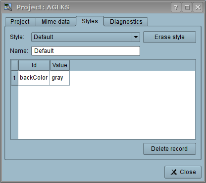
In general the styles are available from the project level. At the level of libraries of widgets you can only define styles fields of widgets. At the project level, at the choice of style it is started the work with styles, which includes access to the fields of styles instead of direct attribute values. In fact, this means that when reading or writing a widget attribute these operations will be carried out with the corresponding field of the chosen style.
When you run the project execution it will be used the set in the project style. Subsequently, the user can select a style from the list of available ones. The user's style will be saved and used next time you run the project.
UI.WebVision
At miss the development tool of the users interfaces that module unneeded for the specific styles implementing.
6.6 Events maps — In plans
This stage implementing for while miss and will perform by the needs.
6.7 The implementation of weak links between data model and presentation(visualization)
During this stage implementation it will be written the additional scripts of the control interface to cover the objectives of the organization of weak links between the model (VCAEngine) and visualizer (Vision). On the side of the visualizer (Vision) it will be complete transition to the weak links with the data model of VCA.
At this stage it was created the missing scripts of control interface and made the full translation of module visualization (Vision) on the weak links. As the result of the operation it was achieved the significant unification of the visualizer and enhance its stability. The question of productivity has remained opened and will be considered later.
6.8 Web-based visualization interface of the project's session
The implementation done into the module UI.WebVision and into volume of execution main primitives and its shapes, for the projects which developed into UI.Vision.