4. Configuration and adjustment of the system
As it can be seen in the section above, OpenSCADA allows configuration for execution in various roles. Support of this possibility is provided by the developed mechanisms for configuration and storage of configuration data. This section contains a description of these mechanisms, designed to demonstrate the flexibility and diversity, thereby allowing to use OpenSCADA to 100%.
In describing the configuration mechanisms and methods of its storage in this section it will be focused the description of system-wide mechanisms. Features of the configuration of modules of subsystems of OpenSCADA are provided in their own module's documentation.
In OpenSCADA it is used the formalized approach to describing the configuration interfaces based on XML. In fact, features of the component's configuration are provided by the component itself, thereby running through the whole system, as the nervous system of the organism. In terms of OpenSCADA it is called the interface of control of OpenSCADA (Control interface). On the basis of the control interface the graphical interfaces of the user configuration are generated by means of modules of OpenSCADA. This approach has the following important advantages:
- Scalability. You can connect only the required configuration modules or use only the remote mechanisms.
- Excluding the need to update the configurators with the addition of new modules/functions, as well as the exclusion of "swelling" of the configurator, providing the support for all of history of now unnecessary and obsolete modules/functions.
- Simplicity of the creation of the graphical interfaces of configuration on the different basis owing to the clear formality.
- The possibility of dynamic configuration is available, ie configuration can be performed directly while the running of the system both locally and remotely, directly controlling the result.
- The simple and special extensibility of the configuration interface by adding the configuration fields on the control interface's description language only in the required components.
In OpenSCADA the three configuration modules on the different basis of visualization are provided. Lets observe them and their configuration options:
- Configuration module on the GUI library Qt (
 http://en.wikipedia.org/wiki/Qt_(framework)) UI.QTCfg. Provides an advanced configuration interface, allowing to operate as a local station and the remote ones in the local and global networks, including secure connection.
- Configuration module based on the dynamic WEB-technologies (DHTML) UI.WebCfgD. Provides an advanced configuration interface, allowing to operate as a local server's station, and the remote stations in the local and global networks, including work on the secure connection. Client connection is provided through the usual Web-browser.
- Configuration module based on the static WEB-technologies (XHTML) UI.WebCfg. Provides an adequate configuration interface that allows to manage the local server's station via the usual Web-browser.
Configuration values, changed in the configurators, as well as most of the data are stored in databases (DB). Given the modularity of subsystems "DB", there can be different database. Moreover, there is the possibility of storing different OpenSCADA parts in different databases of the same type and in the database of different types as well.
In addition to the database configuration information may be contained in the OpenSCADA configuration file, and passed through the command line parameter's when you call OpenSCADA. Saving the configuration in the configuration file is carried out on an equal footing with the database. Standard name of the OpenSCADA configuration file is /etc/oscada.xml. The format of the configuration file and command line parameters we'll examine in the separate section.
Some node's configuration changing will set the modification flag for the node, and also will set active for buttons "Load from DB", for loading the first configuration, and "Save to DB" for the changes saving. The modification flag also rise to parrent node, which allow for restore-save from root node, but real into operations with DB will participate only modified nodes. ![]() A node removing causes to removing it from storage-DB and modification mechanism do not work for this operation.
A node removing causes to removing it from storage-DB and modification mechanism do not work for this operation.
Many of the settings and configuration objects OpenSCADA, which are executed or are already enabled, are not applied immediately, as for changes, because the configuration is read/apply usually only when turn on or start. Therefore to apply the changes, in such cases, it is enough to enable/disable enabled object or to restart the running start/stop. Presently many configurations, which its are not provided applying for now, just are not allowed for editing.
Further examining of the OpenSCADA configuration will be based on the interface of the configurator UI.QTCfg, but the principles of work will be fully consistent with the rest of the configurators owing to the generality in the control interface of OpenSCADA.
We will start examining with the configuration of system parameters of OpenSCADA, which is located in the six tabs at the root page of the station:
- Tab "Station" contains basic information and configuration field of the station, Fig.4a. Here are the provided fields and comments on them:
- ID contains information about the station's identifier. It is specified by the command line parameter "--station". When loading it is sought the section in the configuration file appropriate to the station identifier, and if not detected, it uses the first available one.
- Station name indicates the localized station's name. It is specified by the command line parameter "--statName".
- Program contains information on the program name. Usually it is OpenSCADA or name of solution based on OpenSCADA.
- Version contains the information on the current version of the programme.
- Host name contains the information on the name of the machine that runs the station.
- System user contains the information about the user on whose behalf the program is executed in the system (OS).
- Operation system contains the information about the name and version of operation system, operation system kernel on which the program is executed.
- CPU contains the CPU operative information specifically that is accessible CPU/core number and frequency of the CPU, which runs the program. The value of frequency is checked every 10 seconds, for X86, and allows you to monitor its change, for example, by the power management mechanisms.
- Main CPUs set indicates main list CPUs for use by OpenSCADA tasks. Into round brackets contains list of used CPUs currently.
- Tasks planning clock contains information about the used tasks planning clock and it's resolution on the operation system. It allows you to orient with the minimum interval of time of periodic tasks, for example, for task of data acquisition.
- Internal charset contains information about the charset in which text messages are stored within the program.
- Config file contains information about the configuration file used by the program. Set by the command-line parameter "--config".
- Work directory indicates the working directory of the station. It is used in relative addressing of the objects in the file system, for example, database files. It allows the user to save the modified system data to another database. The value of this field is not stored in the database, but can be changed only in the "WorkDB" section of the configuration file.
- Modules directory indicates the directory of modules for OpenSCADA. If the value of this field is incorrect, then when at start you will not see any graphical interface, but the only information in the console on the correct running of the OpenSCADA kernel.
- Icons directory indicates the directory containing the program icons. If the configuration navigation tree have no icons, then you have incorrectly entered the value of this field.
- Documents directory indicates the directory containing the program documents. If you can not to call local documents then you have incorrectly entered the value of this field or no the documents installed.
- Work DB indicates the working database (DB), namely, the database used to store basic data of the program. Changing of this field notes all objects as modified that allows you to save or to load station's data from the specified main database.
- Save the system at exit points to the need to save the changed data at finishing of the program.
- Save the system period indicates the frequency in seconds with which to save the changed station's data.
- Language indicates the language of program's messages. Changing of this field is acceptable, but leads to a change of messages' language only for the interface and dynamic messages!
- Messages section of the parameters' group that are processing by the work and messages of the stations:
- Least level indicates the level of messages beginning from which they are to be processed. Messages below this level will be ignored. The level "Debug (0)" have special sense, it set will enable debug messages generation by different parts of the system. For the parts debug messages generation control you can use tab "Debug" (fig.4d).
- To syslog indicates the need of sending the message to the system logger, the mechanism of operation system for work with system messages and software. When this option is enabled the possibility appears to manage and control the OpenSCADA messages by the mechanisms of OS.
- To stdout indicates the using as a standard mechanism to display the message the output to the console. Disabling of this feature will eliminate the entire output in the console, unless you specify the following parameter.
- To stderr indicated the using as a standard mechanism to display the message the error output, it is also usually sent to the console.
- To archive indicated the need for output of the messages in the messages' archive of OpenSCADA. This option is usually enabled and its disabling leads to the actual disabling of the archiving at the station.
- Tab "Subsystems" tab contains the list of subsystems (Fig. 4b) and allows you to jump directly to them using the context menu.
- Tab "Redundancy" (Fig. 4c) contains the configuration of redundancy of the station with the following settings:
- Status contains information on redundancy scheme, at the moment this time spent on the execution of one cycle of the task of reserve processing.
- Station level indicates the level of the station in an arrangement (0-255).
- Redundant task period (s) indicates the period of execution of the redundancy task in seconds (1-255).
- Restore connection timeout (s) indicates over the which period of time to attempt to reconnect with a lost redundant station in seconds (0-255).
- Local primary commands transfer enables of local primary commands transfer to the redundant stations for the local changes automatic sync.
- Stations contains the table with information about the redundant stations. Stations can be added and removed via contextual menu. Id of the added stations is to be chosen from the list of available OpenSCADA system stations. Presence into the table at last one enables the redundancy in whole and opens access to pages of the redundancy configuration at level of subsystems, in condition of the subsystem supports the redundancy. The table provides the following information about the station:
- ID ID of the system OpenSCADA station, should be changed after the addition by choosing from the list of available ones;
- Name name of the system OpenSCADA station;
- Live sign of the connection with the redundant station;
- Level level of the remote station in the redundancy scheme;
- Counter requests' counter to the redundant station or waiting time, in the case of the absence of connection.
- Go to remote stations list configuration command to go to the configuration page of the remote OpenSCADA stations in the subsystem "Transports".
- Tab "Tasks" contains the table with opened tasks by OpenSCADA components (Fig.4d). From table you can get several information about the tasks, and also set CPUs for tasks of multi-processors systems.
- Tab "Debug" contains elements for control to debug (Fig.4e) and activates at select the messages level "Debug (0)" or at the objects counters using.
- Tab "Translations" contains elements of the manager of central translations text messages of the system (Fig.4f) and activates at the multi-language mode enabling by base language of text variables set. Elements of the translations manager:
- Text variable's base language is used to activate the support of multilingual text variables by specifying a non-empty basic language. The value of the basic language is selected from the list of bi-character language code, usually only the current and the base language is in the list. Further for the text variables in the non basic language in the tables of the database it will be created the separate columns. Under the text variables the all text fields of configurator, which can be translated into another language are meant. Numbers and other symbolic values are not in their number and are not translated.
- Dynamic translation current state and plan the dynamic text messages translation. The dynamic text messages translation causes the text messages translation cache enabling and requests to the translations to the DB depends to the OpenSCADA system part's language, mostly for multi-language dynamic user interfaces when user has self-preferred language.
- Enable manager enabling the translation manager. Cause the system reloading to forming an index of built translations, however this do not doing to forming full the messages index by deny to reloading some objects into an execution. For full the messages index loading you ought the manager save into enable mode and OpenSCADA restart. Ongoing the system next start will forming full the messages index.
- Languages the translations languages list from base, controls the manager. The language column will contain a data if set language present into source or will not else.
- Source filter the messages filter by substring into the source.
- Check for mismatch toggle checking and indicating to mismatch messages' translation into different places, needs more time for that.
- Messages same the messages table with columns: the base language, selected translation languages, the messages sources. To modify there are allowed the languages columns and at result the changes will set to the messages sources.
To modify the fields of this page it may be required the super user's rights. Get these rights you can by means of including your user into the superuser's group "root", or by entering the station from the superuser "root".
We must mention another one important point: the fields of the identifiers of all OpenSCADA objects are unacceptable for direct editing, because they are keys for storage of objects' data in the database. However, to change the object's identifier you can by the command of cutting and the further pasting of the object (Cut-> Paste) in the configurator.
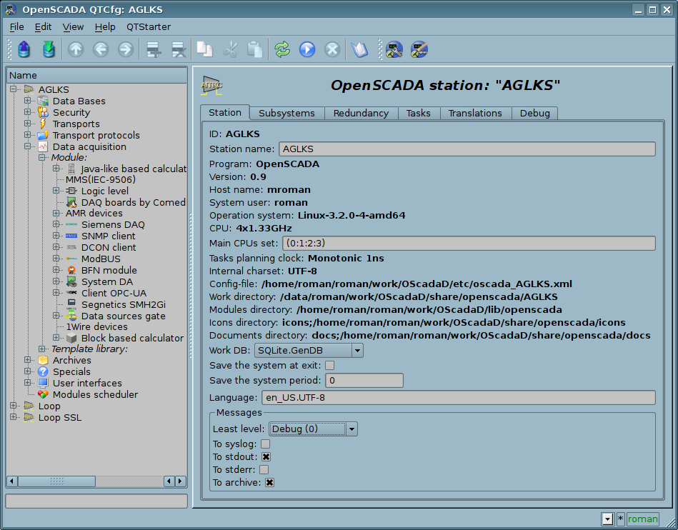
Fig. 4a. The "Station" tab of the main page of the configuration of the station.
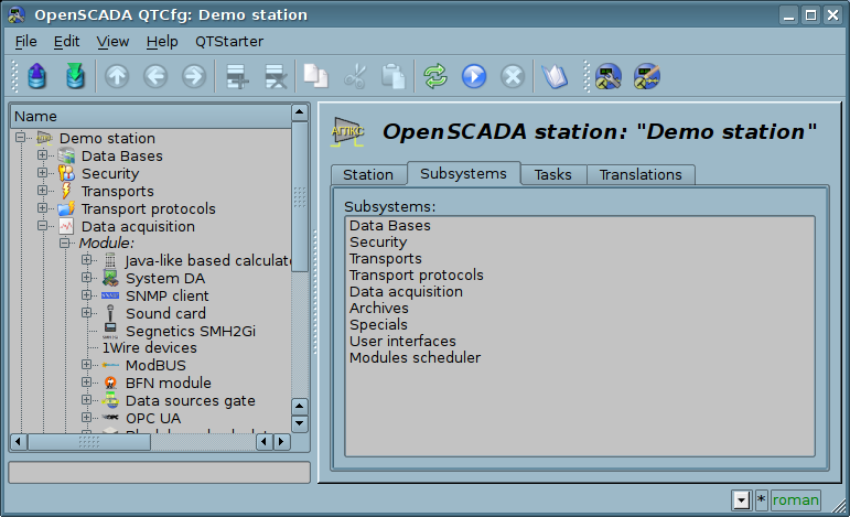
Fig 4b. The "Subsystems" tab of the main page of the configuration of the station.
The service task of the redundancy mechanism is always running and executed at intervals which are prescribed in the appropriate configuration field. The real work on implementing the redundancy is carried out in the presence of at least one redundant station in the list of stations, and implies:
- Monitoring of the connection with external stations. In the monitoring process the requests to remote stations are made to get the information about them updated and to check connection. In the case of loss of connection with the station the repeat of connection to it is made through interval specified in the configuration field "Restore connection timeout". In the "Live" field of the station the current state of communication is displayed. In the "Counter" field the number of requests carried to the remote station, or the time remaining for the next connection attempt to the lost station is displayed. In the "Run" field there is a list of active controllers at the remote station with a sign of the local execution.
- Local planning of the objects' execution in reserve. Planning is carried out in accordance with the station's level and preferences of execution of objects: controllers, messages archivators.
- Calling the data synchronization function for the local objects of the redundant subsystems working in the mode of synchronization of data from the external stations.
There is recommended the redundancy configure in way for DBs of the redundant stations save equal and that will allow you to copy its painlessly to each the station and then to backup only one the DBs set. And the configurations specified to the different stations will save into the configuration file and you can simply configure and change the needed station by the proper configuration file select.
The redundancy configuration start from the redundant stations appending to list of system stations OpenSCADA in tab "Subsystem" of the subsystem "Transports" (Fig.4.3b). And to add here needs not only the redundant stations to the current one but the same current one with its external IP, that is some loop. Further this configurations will have been stored into the generic DB of the redundant system, and from this time the DBs will be used for that all redundant station creation. Then there is important to make on that stage all needed changes into the generic DB and about this project in general!
Next for the concrete station, with copy of the generic DB, we configure its specific parameters into the tab "Redundancy" of the main page (Fig.4c), which will be stored into the configuration file.
After that all next configurations of redundancy perform into the tab "Redundancy" of proper subsystem, "Data acquisition" (Fig.4.5b) or "Archives" (Fig.4.6b). If you will set the parameter "Local primary commands transfer" (Fig.4c) then the configurations, like to any other generic configurations, can be performed at any one from the stations and all the performed changes will be transferred to all other ones, sure if its are available.
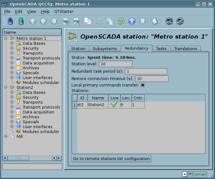
Fig 4c. The "Redundancy" tab of the main page of the configuration of the station.
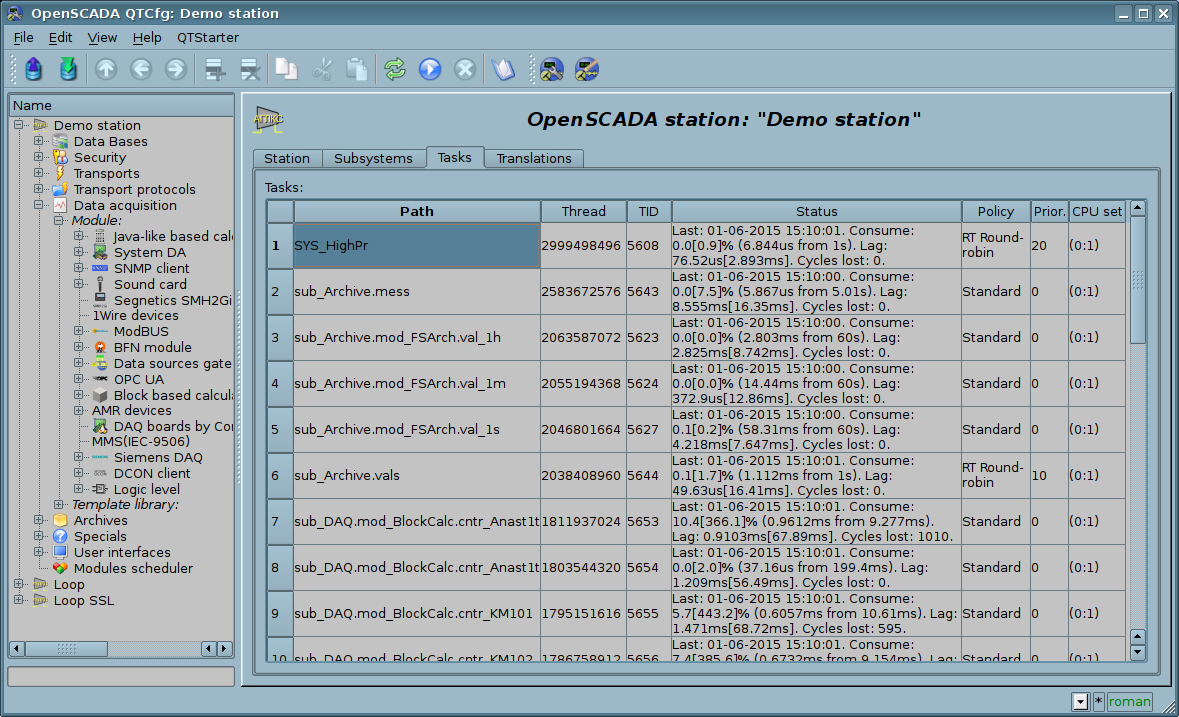
Fig 4d. "Tasks" tab of the main page of the configuration of the station.
For OpenSCADA different working specific debug you may be necessary to enable addition-debugging messages generation, which you can set by select minimal messages level, into tab "Station", to "Debug (0)". As a result of this will emerge tab "Debug" (fig.4e) where available the objects counters for control to leaks, and also the table with incoming debug messages' categories list. Into the table you can select only needed debug messages sources and omit to overload the archiving messages subsystem and overall the system performance decrease. You can also select higher categories, up to root system category, that will disable detailed selection and enable all messages generation by the level or by overall system. For the debug messages observing you need to go subsystem "Archives" (fig. 4.6c), and for this provided button "See to messages". Selected debug mode and debug categories list can be standard stored to configuration file and on next boot the debug mode will be activated, this important primarily for the objects counters.
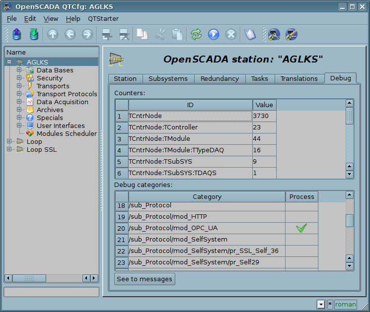
Fig. 4e. The "Debug" tab of the main page of the configuration of the station.
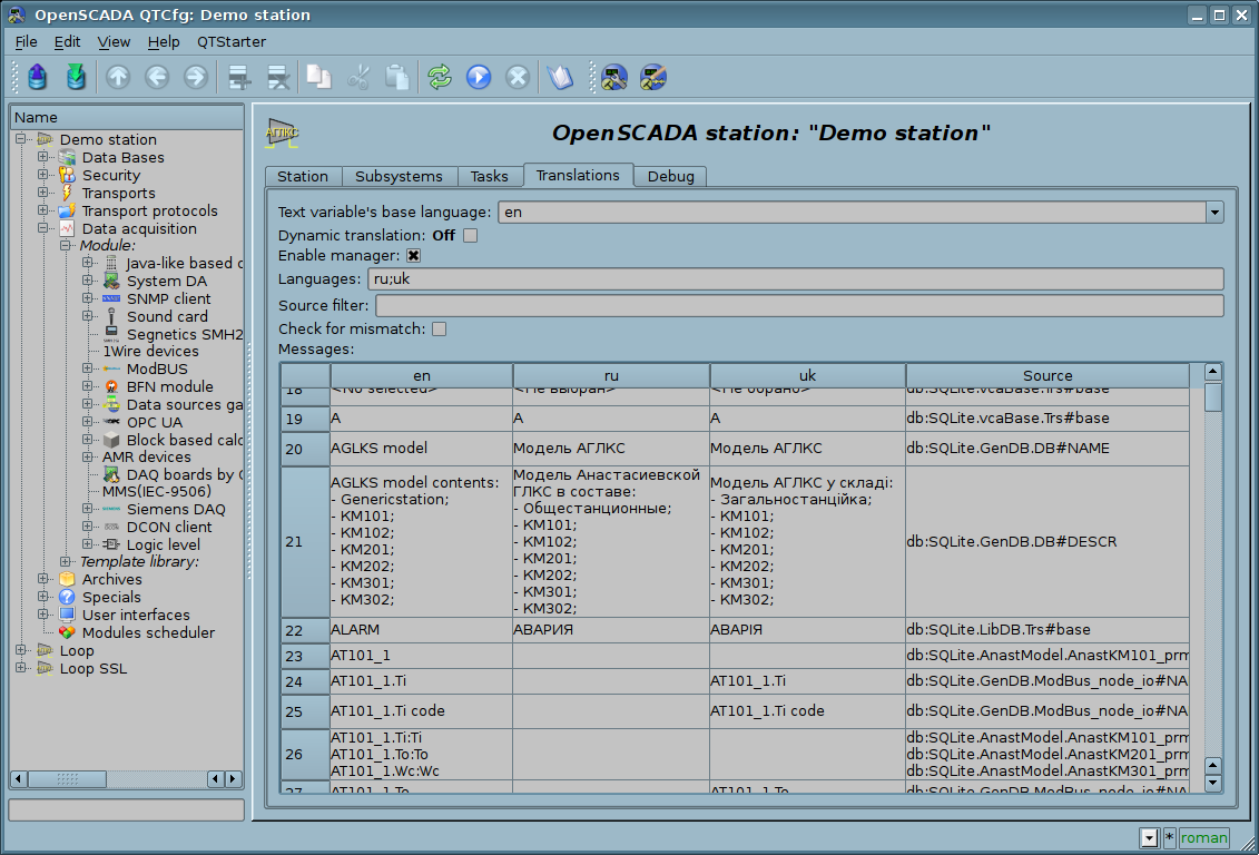
Πθρ. 4f. The "Translations" tab of the main page of the configuration of the station.
While examining the configuration pages of modular subsystems there will be described the general for all modules properties. However, it should be noted that each module can provide both: the additional tabs, and separate fields for the configuration of their own functioning for the pages, objects of which are inherited by modules. Information on the features and additions of the modules can be found in separate documentation for each of them.
4.1. "DB" subsystem
The subsystem is the modular one and contains a hierarchy of objects depicted in Figure 4.1a. To configure the subsystem the root page of the subsystem "DB" containing the tab "Modules". Tab "Modules" (Fig. 4.1b) contains the list of modules in subsystem "DB", available at the station.
To modify the page's fields of this subsystem it may be required the super user's rights or the inclusion of your user to the "DB" group.
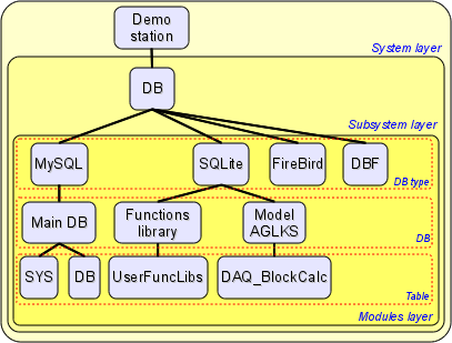
Fig. 4.1a. The hierarchical structure of "DB" subsystem.
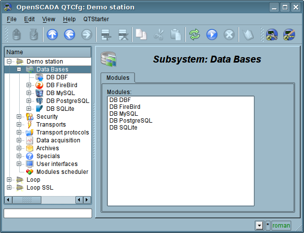
Fig. 4.1b. Tab "Modules" tab of the root page of "DB" subsystem.
Each module of the "DB" subsystem provides the configuration page with the following tabs: "DB" and "Module". "DB" tab (Fig. 4.1c) contains the list of databases registered in the module and the flag of the sign of full deleting of the database when making the delete command. In the context menu of the databases' list the user is provided with an opportunity to add, delete and move to the desired database. The "Module" tab contains information about the module of the "DB" subsystem (Fig.4.1d):
- Module module's identifier.
- Name module's name.
- Type module's type, subsystem's identifier, which contains the module.
- Source shared library the source of the module.
- Version module's version.
- Author module's author.
- Description module's short description.
- License license agreement of module's distribution.
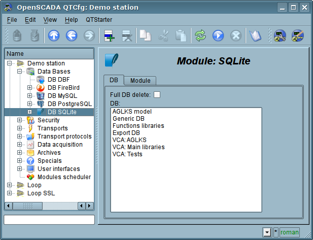
Fig. 4.1c. "DB" tab of the module of "DB" subsystem.
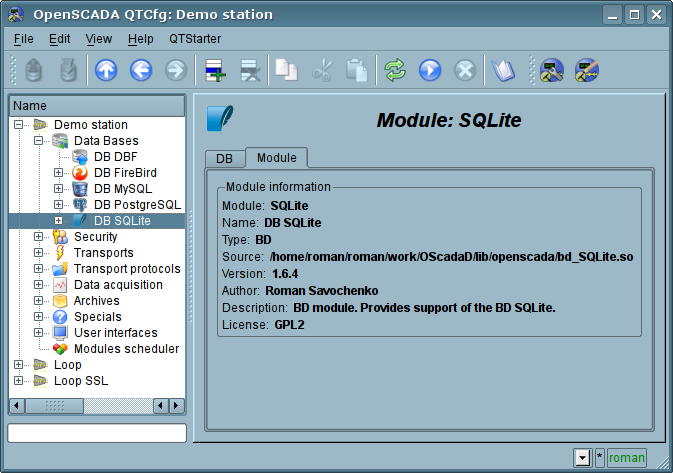
Fig. 4.1d. "Module" tab of the module of the "DB" subsystem.
Each database contains its own configuration page with the tabs "Data base", "Tables" and "SQL", in case SQL-requests support. Besides the basic operations you can copy the contents of the DB by means of the standard function for the copying the objects in the configurator. The copying operation the DB contents involves the copying of the original database to the destination database, and the contents of the destination database is not cleared before the copy operation. Copying the contents of database is made only when the both databases are enabled, otherwise it will run a simple copy of the object of the database.
Tab "Data base" (Fig.4.1e) contains the main configuration options of the DB as follows:
- Section "State" contains the properties which characterize the DB status:
- Enable DB status "Enable".
- Accessible tables list of tables that are in the database. Context menu of the property gives the opportunity to physically remove the tables from the database.
- Load system from this DB command to make load from this database. Can be used when transferring data in the database between stations. For example, you can save the section of one station in the export database, physically to move the DB to another station and connect it in this subsystem, and call this command.
- Section "Config" contains the following configuration fields:
- ID contains the information on the DB identifier.
- Name specifies the DB name.
- Description short description of the DB and it's appointment.
- Address DB address in the specific for the database type (module) in the format. Format Description of the DB address recording format is usually available in the tooltip for this field.
- Code page indicates the code page, in which the text values of database are stored and provided. The value of the code page of database in conjunction with the internal code page of the station is used for clear transcoding of the text message while exchange between the station and the database.
- To enable indicates the state "Enable", in which to set the DB when start.
Tab "Tables" (Fig.4.1f) contains the list of the opened pages. In normal mode of the program operation this tab is empty, because after the completion of working with tables the program closes them. The presence of opened tables tells that the program is now working with tables or tables are opened by the user to examine their contents. In the context menu of list of opened tables you can open the table for study (the command "Add"), close the opened page (the command "Delete") and proceed to examination of the contents of the table.
Tab "SQL" (Fig.4.1g) allow only for data bases which support SQL-requests, and contains field to request enter, button to request send and table to result. To control the request transaction context provided by separate configuration field.
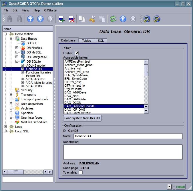
Fig. 4.1e. Tab "Data base" of the DB of module of subsystem "DB".
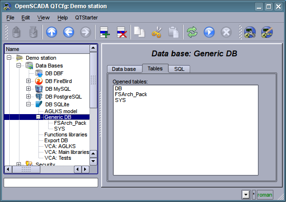
Fig. 4.1f. Tab "Tables" of the DB of module of subsystem "DB".
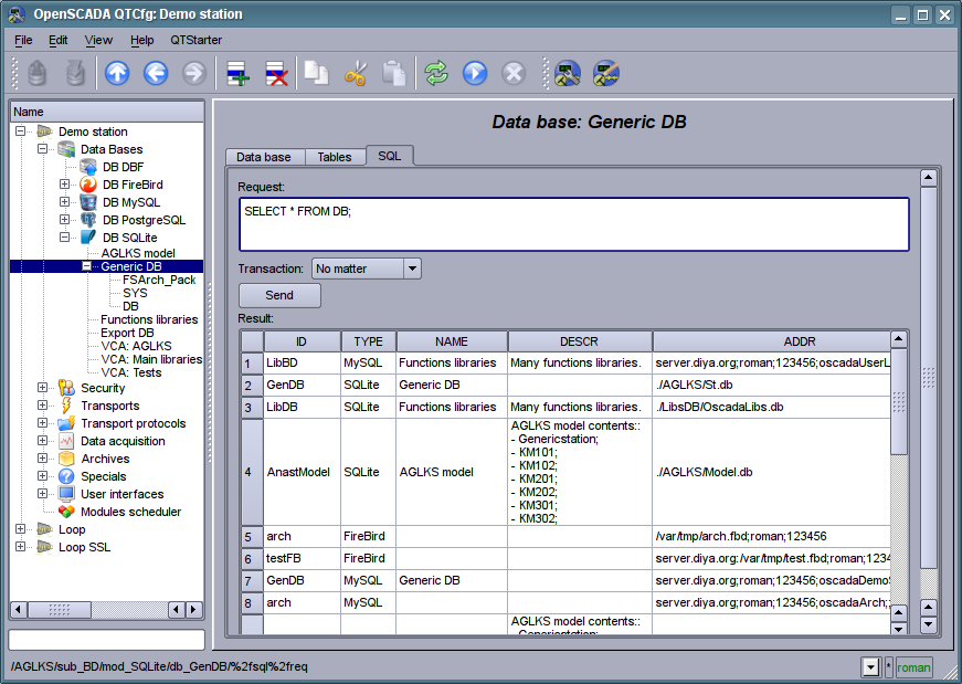
Fig. 4.1g. Tab "SQL" of the DB of module of subsystem "DB".
Page of the examination of the contents of the table contains only one tab, "Table". Tab "Table" (Figure 4.1h) contains the field of the name of the table and the table with the contents. Table of contents provides the following functions:
- table's cells content redaction;
- addition of the line;
- deleting of the line.
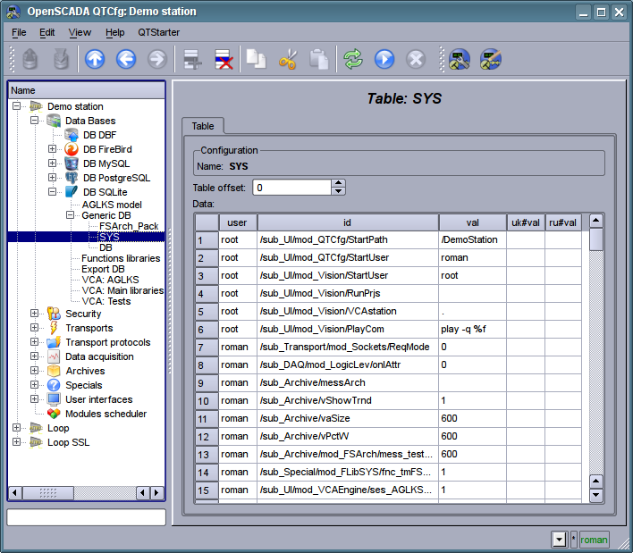
Fig. 4.1h. Tab "Table" of the DB table of the module of the subsystem "DB".
4.2. Subsystem "Security"
The subsystem is not modular one. To configure the subsystem the root page of the subsystem "Security" is provided, which contains the tab "Users and Groups". Tab "Users and Groups" (Figure 4.2a) contains the list of users and users' groups. Users in the group "Security" and with the rights of the privileged user can add, delete the user or group of users. All other users can go to the page the user or the users' group.
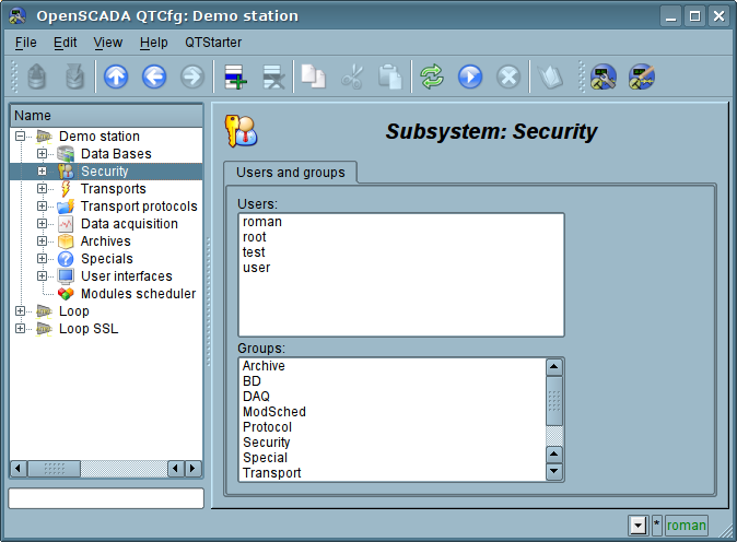
Fig. 4.2a. Tab "Users and Groups" of the root page of the subsystem "Security".
To configure the user it is provided the page containing only the tab "User" (Fig.4.2b). Tab contains the configuration data of the user's profile, which can be changed by the user itself, the user of the "Security" group or the privileged user:
- Name information about the name (identifier) of the user.
- Full name specifies the full name of the user.
- Description description and random information about the user.
- Password the field to change the user's password. It always displays "******".
- Language user's language for the dynamic messages context and for text to speech of the user interface. Empty to the system language.
- User picture specifies the user's picture. Picture can be loaded and saved.
- Groups the table with a list of user groups of the station and with the sign of identity of the user to the groups.
- User DB DB address for the user's data storage.
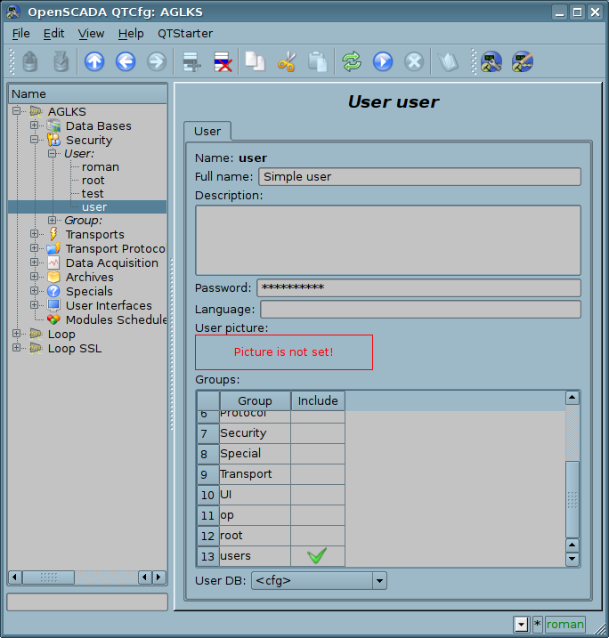
Fig. 4.2b. The tab "User" of the user's page of "Security" subsystem.
To configure the user's group it is provided the page containing only the tab "Group" (Fig.4.2c). Tab contains the configuration data of the group's profile, which can be changed only by the privileged use:
- Name information about the name (identifier) of the user's group.
- Full name specifies the full name of the user's group.
- Description description and random information about the users group.
- Users list of users included in this group. With the context menu of the list you can add or remove the user in the group.
- User group DB DB address for the user group's data storage.
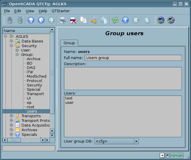
Fig. 4.2c. The tab "Group" of the user's group page of "Security" subsystem.
4.3. Subsystem "Transports"
The subsystem is the modular one and contains the hierarchy of objects shown in Figure 4.3a. To configure the subsystem it is provided the root page of the subsystem "Transports", containing the tabs "Subsystem" and "Modules".
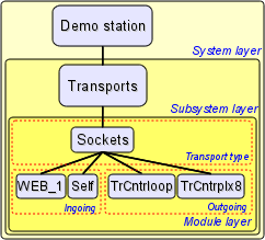
Fig. 4.3a. The hierarchical structure of subsystems "Transports".
The tab "Subsystem" (Figure 4.3b) contains the configuration table of the external stations for a given OpenSCADA. External stations can be the system, user and both ones that is selected by the appropriate column. System's external stations are available only to the super user and are used by the components of the system purpose, for example, the mechanism of the horizontal redundancy and module DAQ.DAQGate. User's external stations are tied to the user who created them, and thus the list of user's external stations is individual for each user. User's external stations are used by the components of graphical interface, for example, UI.QTCfg, UI.WebCfgD and UI.Vision. In the table of the external stations it is possible to add and delete records about the station, as well as their modification.
Each station contains the following fields:
- Id identifier of the external station.
- Name the name of the external host.
- Transport the combobox of the subsystem's module "Transports" for the using of it when access to the external station.
- Address address of the external station if the format, specific to the chosen in the previous field of the module of the subsystem "Transports".
- User the name/identifier of the user of the external station on behalf of whom to perform the connection.
- Password password of the user of the external station.
- Mode The host mode: "User", "System", "User and System".
- Uprising level Uprising hosts level of the pointed host for possibility of the requests re-transmission.
Tab "Moules" tab (fig. 4.1b) contains the list of modules in subsystem "Transports" and it is identical for all modular subsystems.
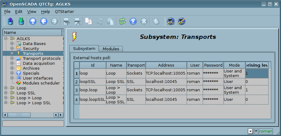
Fig. 4.3b. Tab "Subsystem" of the root page of subsystem "Transports".
Each module of the subsystem "Transports" provides the configuration page with the tabs "Transports" and "Module". The tab "Transports" (Fig.4.3c) contains the list of incoming and outgoing transports registered in the module. The context menu of lists of transports provides the user with the possibility to add, delete and move to the desired transport. On the "Module" tab it is provided the information about the module of subsystem "Transports" (Fig. 4.1d), whose structure is identical for all modules.
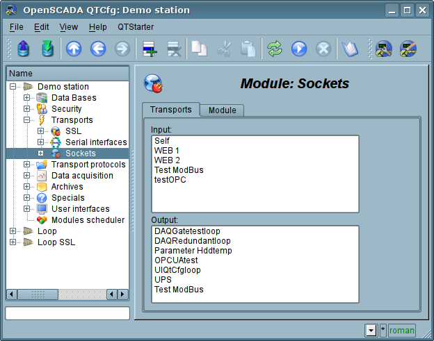
Fig. 4.3c. The tab "Transports" of the module of subsystem "Transports".
Each transport contains its own configuration page with one tab "Transport". This tab contains the basic settings of transport. Incoming transport (fig.4.3d) includes:
- Section "State" contains the settings that characterize the state of the transport:
- Status information on the current transport's status and statistics of its work.
- Running state of the transport "Running".
- Transport DB DB address to store the transport's data.
- Section "Config" directly contains the configuration fields:
- ID information on the transport's identifier.
- Name specifies the transport's name.
- Description brief description of the transport and its appointment.
- Address transport's address in the specific for the type of transport (module) format. Description of the record format addresses transport, as a rule, is available in the tooltip for this field.
- Transport protocol indicates the transport protocol module (subsystem "Transport protocols") that should work in conjunction with the input transport. Ie the received unstructured data this module will sent to the structuring and processing to the specified module of the transport protocol.
- To start indicates the status of "Running", in which to transfer the transport at startup.
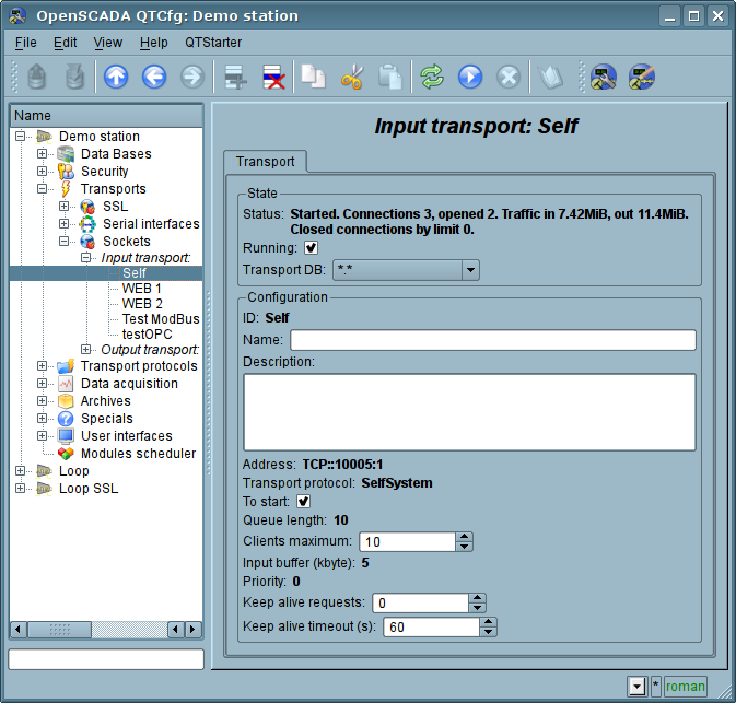
Fig. 4.3d. Tab "Transport" of the page of incoming transport of module of subsystem "Transports".
Outgoing transport (Fig. 4.3e) contains:
- Section "State" contains the settings that characterize the state of the transport:
- Status information on the current transport's status and statistics of its work.
- Running state of the transport "Running".
- Transport DB DB address to store the transport's data.
- Section "Config" directly contains the configuration fields:
- ID information on the transport's identifier.
- Name specifies the transport's name.
- Description brief description of the transport and its appointment.
- Address transport's address in the specific for the type of transport (module) format. Description of the record format addresses transport, as a rule, is available in the tooltip for this field.
- To start indicates the status of "Running", in which to transfer the transport at startup.
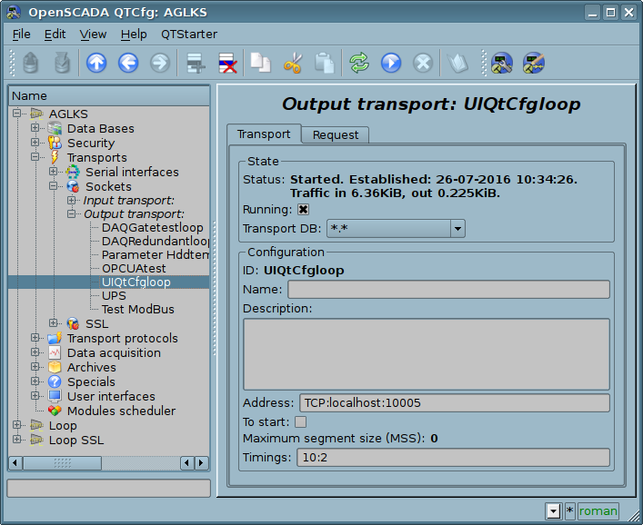
Fig. 4.3e. Tab "Transport" of the page of outgoing transport of module of subsystem "Transports".
Outgoing transport, in addition, provides the tab for forming the user request via this transport (Fig.4.3f). The tab is provided for setting communication, as well as for debugging the protocols and includes:
- Time (ms) information about the time taken for request and receiving the answer.
- Mode indicates the regime of data from the following list: "Binary", "Text(LF)", "Text(CR)", "Text(CR/LF)", in which the request will be formed and the answer will be provided. In binary mode data is recorded in pairs of numbers in hex, ie bytes, separated by spaces.
- Timeout wait sign for expect by timeout when a response is received. Many systems in response to various protocols (HTTP) are send the response data in several pieces. Without this flag will be received and displayed only the first piece. When this flag will be set all the pieces awaiting an answer, until the lack of data during the timeout the transport elapsed .
- Input buffer size, bytes control of the input buffer size and the reading disabling (0) at all, only writing.
- Send command to send a request.
- Request contains the request in the selected mode of data representing.
- Answer provides the answer in the selected mode of data representing.
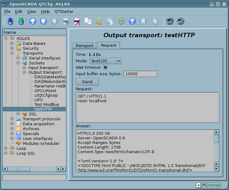
Fig. 4.3f. The tab "Request" of the page of outgoing transport of module of subsystem "Transports".
4.4. Subsystem "Transport protocols"
The subsystem is modular. To configure the subsystem the root page of the subsystem "Transport Protocols" is provided, it contains tab "Modules". The tab "Modules" (Fig. 4.1b) contains the list of modules in subsystem "Transport Protocols" and is identical for all modular subsystems.
Each module of subsystem "Transport Protocols" provides configuration page with the only one tab "Module". On the tab "Module" there is the information on the module of subsystem "Transport Protocols" (Fig. 4.1d), which structure is identical for all modules.
4.5. Subsystem "Data acquisition"
The subsystem is modular and contains the hierarchy of objects depicted in Fig.4.5a. To configure the subsystem the root page of subsystem "Data acquisition" is provided, which contains the tabs "Redundancy", "Template libraries" and "Modules".
To obtain access to modify the objects of this subsystem the user of the group "DAQ" or the rights of the privileged user are required.
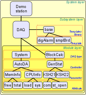
Fig. 4.5a. The hierarchical structure of subsystem "Data acquisition".
As a redundancy object of the subsystem "Data Acquisition" there used the object of controller for which the redundancy process performs that functions:
- Redundancy of the data acquisition mechanism. Typically, this function is realized without special arrangements by simply running of the parallel redundancy stations with the same configuration and working independently. However, in the case at the station, which works as PLC, such approach is unacceptable because of the simultaneous making of control actions and the absence of synchronization of calculators' data.
- Compensation of the data loss on the time of the node stop with the redundant node archive. There are two mechanisms of compensation. The first and the main mechanism implements the loading of the sections of the archive from the redundant station at the time of the station startup in general or of individual controller's objects. The section of the archive is requested from the moment of the last record in the local archive and till the current time. The depth of the request is limited by the indicating of the limit time in the configuration of the redundancy. The second, complementary mechanism, performs the filling of the "holes" in the archive at the time of the actual user's request to the data. Such an approach on the one hand allows to make the predictable in time synchronization at startup and on the other hand it's actually eliminates the data loss in the case of working at least one station during the entire time.
- Load distribution of data acquisition between the nodes. When creating complex allocated systems there can be an important question of predicting and optimizing of the overall system performance. Taking into account these problems the redundancy mechanism provides the execution of tasks of data acquisition of individual sources (OpenSCADA controllers) only at one station. The other stations' tasks would go to data synchronization mode with the executive station. In the case of loss of the connection with the executive station the task of the local data acquisition is started. It's also provided the possibility of optimal the load distribution of the execution of data acquisition task's of the controllers' group between the stations.
- Optimization of the load on the external data sources through the data request from an external source by the only one node. In practice, we often meet highly loaded data sources or interfaces of access to the data sources, for which even the data acquisition by one station can be a problem and would require reducing the acquisition periodicity, i.e. data quality. The mechanism of redundancy, besides the load distribution between the stations as described above allows you to remove an additional load form the data source and its interfaces, thereby improving the quality of data. Writing to attributes of the controller's object under redundancy causes to the modification request sending to the master one, that is through it.
- Prevention of some differences of data on different nodes associated with the mismatch of moments of time at the independent acquisition of data by individual nodes by means of receiving the data from the station with an active controller. In systems of high accountability under the redundancy there should be excluded or minimized the differences in the data at different stations, that means the real acquisition of data by one station and synchronization with these data of other ones.
Tab "Redundancy" (Fig. 4.5b) presented only if at last one station pointed into the redundancy and contains the configuration of redundancy of data sources of subsystem "Data acquisition" with the following settings:
- Restore data depth time (hours) indicates the maximum depth of archival data to restore from the archive of the remote station when start up in hours (0-12).
- Controllers contains the table with the list of controllers, available for redundancy, and their current status:
- Controller full controller's ID;
- Name controller's name;
- Started the sign of the controller's execution on the local station;
- Redundant redundancy mode of the controller, you can select it from the list:
- "Off" absolutely independent working of the controller's object.
- "Asymmetric" full redundancy with the allowed controller's object configuration of the remote station and without tries to generalize its.
- "Only alarms" in fact it is working without a redundancy, but with alarms oppressing from the reserve controller's object to exclude a duple messages into the alarms.
- Preferable run configuration of the preferred execution at the specified station can be changed; reserved values:
- <High Level> execution at the station with the highest level.
- <Low Level> execution at the station with the lowest level.
- <Optimal> the choice for the execution of the least loaded station.
- Remoted sign indicating the execution of the controller on the remote station and work the local station in mode with a remote data synchronization.
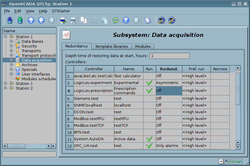
Fig. 4.5b. Tab "Redundancy" tab of subsystem "Data acquisition".
The tab "Template libraries" (Fig.4.5c) contains the list of libraries of templates for the parameters of this subsystem. In the context menu of the list of template libraries the user can add, delete and move to the desired library. The tab "Modules" (Fig. 4.1b) contains the list of modules in the subsystem "Transports" and is identical for all modular subsystems.
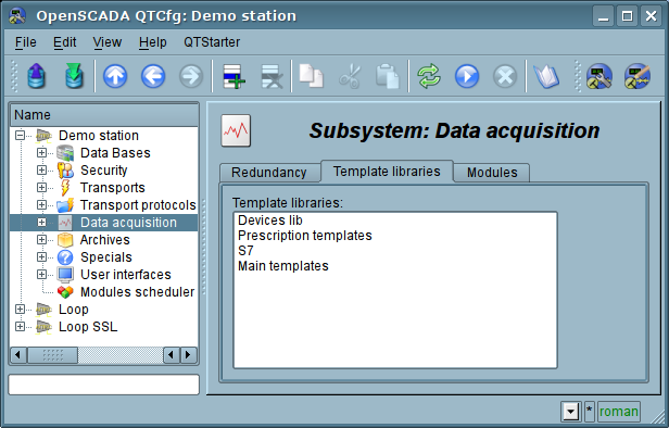
Fig. 4.5c. The tab "Template libraries" of the subsystem "Data acquisition".
Each template library of subsystem "Data acquisition" provides the configuration page with the tabs "Library" and "Parameter templates". Tab "Library" (fig. 4.5d) contains the basic settings of the library:
- Section "State" contains properties that characterize the state of the library:
- Accessing state of library "Accessing".
- Library DB address of the database for data storage of the library and templates.
- Date of modification date and time for the object last modification.
- Section "Config" directly contains the configuration fields:
- ID information on the ID of the library.
- Name specifies the name of the library.
- Description short description of the library and its purpose.
Tab "Parameter templates" (Fig.4.5e) contains the list of templates in the library. In the context menu of the list the user can add, delete and move to the desired template.
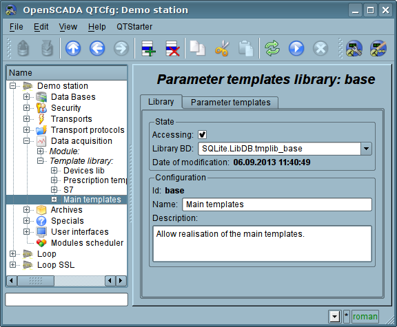
Fig. 4.5d. The main tab of configuration of template library of subsystem "Data acquisition".
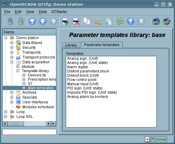
Fig. 4.5e. The tab of the list of templates in the template library of subsystem "Data acquisition".
Each template of the template library provides the configuration page with the tabs "Template" and "IO". The tab "Template" (Figure 4.5f) contains the basic settings of the template:
- Section "State" contains properties that characterize the state of the template:
- Accessing state of template "Accessing".
- Used counter of the template's using. Allows you to determine whether the template is used and, consequently, the ability to edit the template.
- Date of modification date and time for the object last modification.
- Section "Config" directly contains the configuration fields:
- ID information on the ID of the template.
- Name specifies the name of the template.
- Description short description of the template and its purpose.
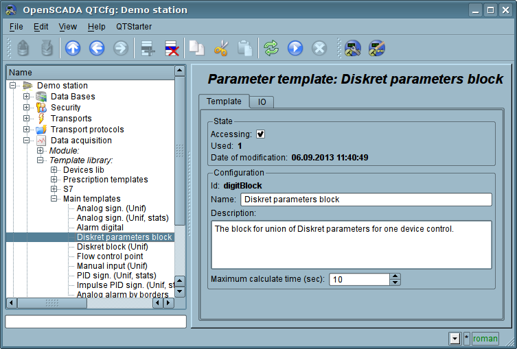
Fig. 4.5f. The main configuration tab of the parameters template of subsystem "Data acquisition".
The tab "IO" (Fig.4.5g) contains the configuration of attributes (IO) of templates and the program of template on the one of languages of the user programming of OpenSCADA, for example, DAQ.JavaLikeCalc.JavaScript. To the table of attributes of template user can, through the context menu, add, insert, delete, move up or down the record of attribute, as well as edit the attribute's fields:
- Id ID of the attribute.
- Name the name of the attribute.
- Type select the value's type of the attribute from the following: "Real", "Integer", "Boolean", "String", "Text", "Object".
- Mode select the mode from list: "Input", "Output". Typically used to indicate the direction of data transmission through link. Ie, values for "Input" data link will only be obtained, and for the "Output" will also be transferred, in the case of modification.
- Attribute mode of the parameter's attribute, implemented based on a template from the list: "No attribute" ,"Read Only","Full access". For the attributes of a template, in which this field is set, it will be created an appropriate attribute in the controller's parameter of this subsystem.
- Configure configuration mode of the attribute in the configuration tab of a template of the controller's parameter of this subsystem from the list: "Constant", "Public constant", "Link". In "Public constant" and "Link" modes tab in the configuration tab of the template will be added these attributes to set the constant or specify an external link of the parameter.
- Value attribute's default value or template of the links to access by the link. The format of the link's template depends on the component that uses it. Usually for the module DAQ.LogicLev the link's template is written the following way: {Parameter}|{attribute}. Field {Parameter} specifies the parameter's name as the attribute's container. Attributes with the equal value {Parameter} will be grouped and will be appointed only by the indication of attributes' container, and individual attributes will be associated with the attributes of the container in accordance with the field {attribute}.
The syntax of the language of the template's program you can see in the documentation of the module, providing an interpreter of the chosen language. For example, a typical user programming language of OpenSCADA DAQ.JavaLikeCalc.
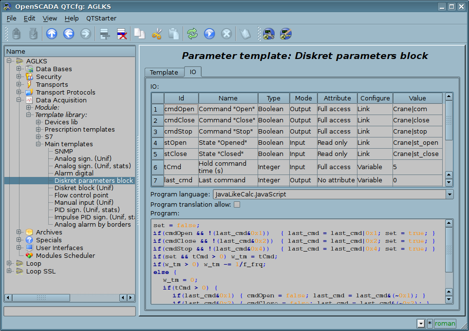
Fig. 4.5g. The configuration tab of the attributes and template's program of subsystem "Data acquisition".
Each module of the subsystem "Data acquisition" provides the configuration page with the tabs "Controllers" and "Module". The tab "Controllers" (Fig.4.5h) contains the list of controllers, registered in the module. In the context menu user can add, delete and move to the desired controller. The tab "Module" provides information about the module of the subsystem "Data acquisition" (Fig. 4.1d), which structure is identical for all modules.
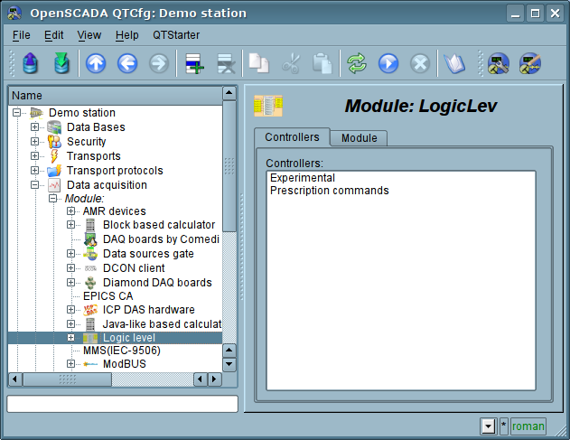
Fig. 4.5h. The tab "Controllers" of the module of the subsystem "Data acquisition".
Each controller contains its own configuration page with the tabs "Controller" and "Parameters".
The tab "Controller" (Fig.4.5i) contains the basic settings. The structure of these settings may differ slightly from one module of this subsystem to another, as you can find in the own documentation of modules. As an example, lets examine the settings of the controller in the module of the controller of logic DAQ.LogicLev:
- Section "State" contains the properties, which characterize the state of the controller:
- Status specifies the controller's status. In our case, the controller is running and the computation time is 425 microseconds.
- Enable the state of the controller "Enable". When enabled, the controller provides the possibility of creating the parameters and their configuration.
- Run the state of the controller "Run". The running controller performs the physical data acquisition and/or includes mechanisms for access to these data.
- Controller DB the address of the database for data storage of the controller and its parameters.
- Section "Config" directly contains the configuration fields:
- ID information on the controller's identifier.
- Name specifies the controller's name.
- Description brief description of the controller and its purpose.
- To enable indicates the status of "Enable" in which to transfer the controller at startup.
- To start indicates the status of "Run" in which to transfer the controller at startup.
- Parameters tables names of tables that store the parameters of different types (refers to parameter objects of data acquisition).
- Calc schedule defines a periodic or scheduled character of calculations. In our example this one second of calculation template.
- Request task priority sets the priority of data acquisition of this controller. It is used when scheduling the operating system tasks. In the case of proper access availability this field includes the planning of the controller's task in real time and with the specified priority otherwise it modifies parameter "nice" of the task.
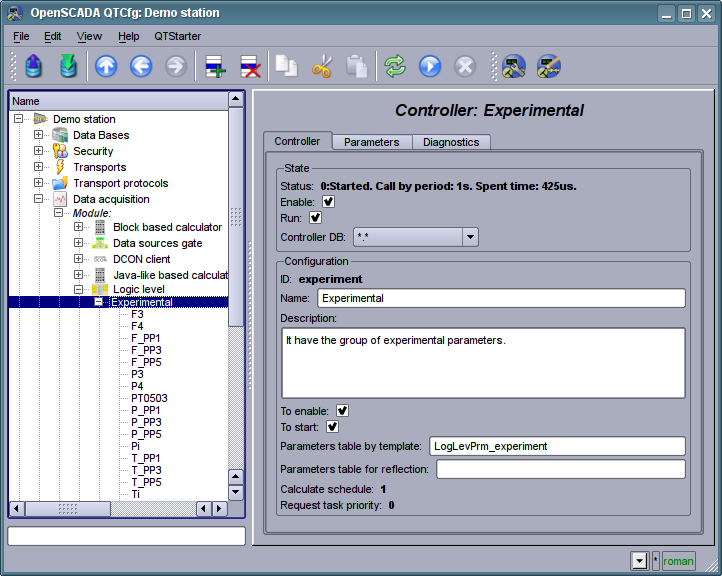
Fig. 4.5i. The main configuration tab of the controller of subsystem "Data acquisition".
"Parameters" tab (Fig.4.5j) contains a list of parameters in the controller, select the type of parameters that are created by default, as well as information on the total number and the number of enabled parameters. In the context menu user can add, delete and move to the desired parameter.
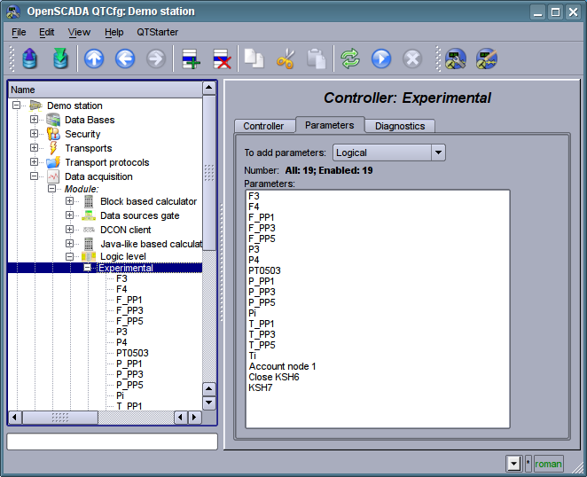
Fig. 4.5j. "Parameters" tab of the configuration page of the controller of subsystem "Data acquisition".
"Diagnostic" tab (Fig.4.5k) contains diagnostic messages form by the data source. More data sources is external devices with accessing to the data by a network connection or a system bus then there possible different emergency situation on access to the data. Print all its to field "State" of controller object impossible due it display only current access data state. Due the diagnostic you can trace all emergency situation at messages view, which forming by the controller object for specified period of time and by selected messages level. Besides to certain diagnostic information some modules of data sources can provide here debug exchange dumps, on messages level "Debug (0)".
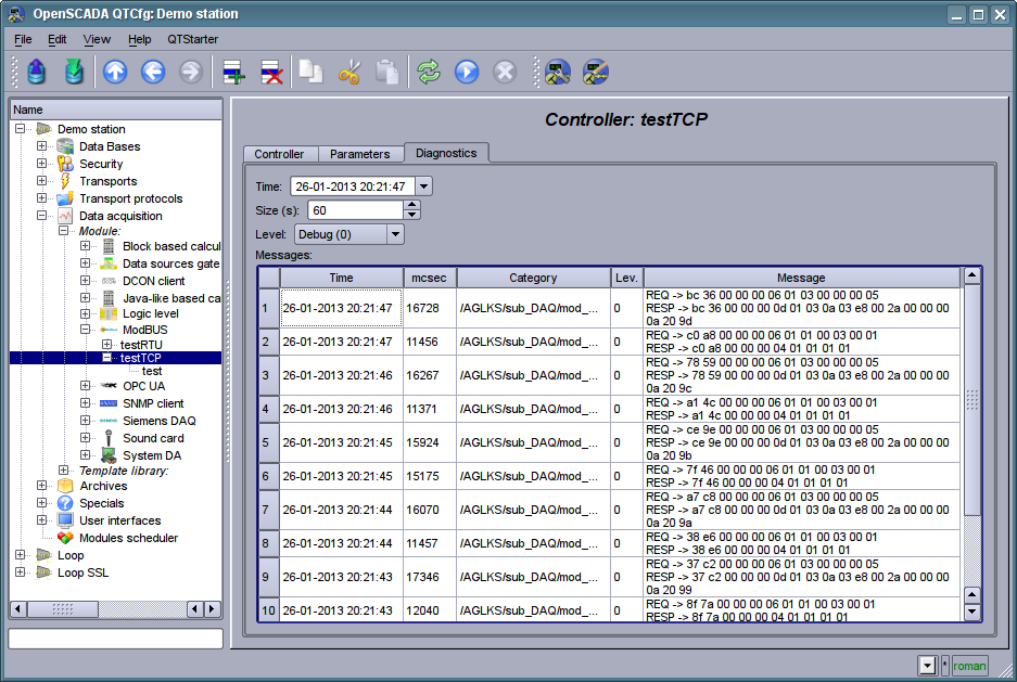
Fig. 4.5k. "Diagnostic" tab of configuration page of the controller of subsystem "Data acquisition".
Parameters of the controllers of subsystem "Data acquisition" provides the configuration page with the tabs "Parameters", "Attributes", "Archiving" and "Template config". The tab "Template config" is not standard, but it is present only in the parameters of modules of subsystem "Data acquisition", which implement the mechanisms of working under the template in the context of the data source, which they are served, for logical type. In this review this tab is included for logical completeness of the review of the configuration of templates of parameters of subsystem "Data acquisition" and as the final stage using.
The tab "Parameter" (Fig.4.5l) contains the main settings:
- Section "State" contains the properties, which characterize the state of the parameter:
- Type specifies the type parameter. Type of disabled parameter can be changed if there are multiple types.
- Enable the state of the parameter "Enable". Enabled parameter is used by the controller fro data acquisition.
- Section "Config" directly contains the configuration fields:
- ID information on the parameter's identifier.
- Name specifies the parameter's name.
- Description brief description of the parameter and its purpose.
- To enable indicates the status of "Run" in which to transfer the parameter at startup.
- Parameter template the address of the previously discussed template.
The tab "Attributes" (Fig.4.5m) contains the parametr's attributes and their values in accordance with the configuration of the used template and calculation of its program.
The "Archiving" tab (Fig.4.5n) contains the table with the attributes of a parameter in the columns and the archivers in rows. The user can set the archiving for the desired attribute with the required archiver simply by changing the cell at the intersection.
The "Template config" tab (Figure 4.5o) contains the configuration fields in accordance with the template. In this example it is the group link on the external parameter. This link can be set simply by pointing the way to the parameter if the flag "Only attributes are to be shown" is not set, or to set the addresses of the attributes separately in the case if the flag is set. Sign "(+)", at the end of the address signals about successful linking and presence of the target.
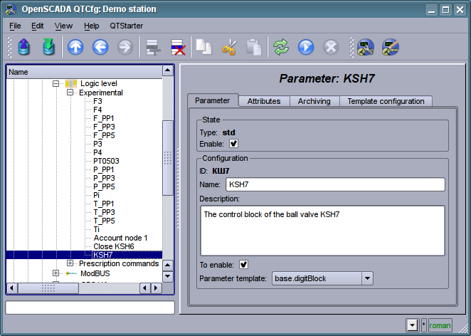
Fig. 4.5l. The main configuration tab of the parameter of the controller of subsystem "Data acquisition".
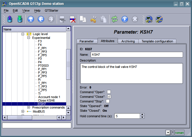
Fig. 4.5m. The "Attributes" tab of the parameter of the controller of subsystem "Data acquisition".
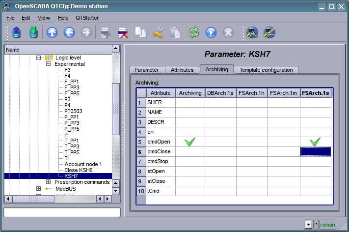
Fig. 4.5n. The "Archiving" tab of the parameter of the controller of subsystem "Data acquisition".
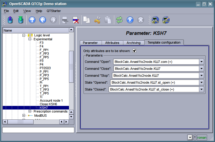
Fig. 4.5o. The "Template config" tab of the parameter of the controller of subsystem "Data acquisition".
4.6. Subsystem "Archives"
The subsystem is modular and contains the hierarchy of objects depicted in Fig.4.6a. To configure the subsystem the root page of the subsystem "Archives" is provided, it contains tabs: "Redundancy", "Messages archive", "Value archives" and "Modules".
To gain the access to modify the objects of this subsystem the user of the group "Archive" or the privileged user rights are required.
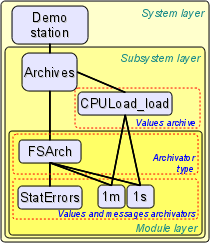
Fig. 4.6a. The hierarchical structure of subsystem "Archives"
In a role of the redundancy object of the subsystem there used the object of messages archivator and there in the redundancy and synchronization performs preparing of a request of the data for the remote station for the messages from the time of the last request. On start there performed an initial synchronization which provides a request of the active data (messages) from a first active station into the list and to depth of the data missing into the archive from the current time but not more to the pointed limit into the configuration. Writing messages to a reserve archive causes to redirection the writing request to the master station both for new and rewriting messages (also the messages write locally). Rewriting messages to a master archive causes to the messages distribution of all the reserve station. For alarming messages, negative level, at its writing performs an additional processing for the active alarms, that is only old original ones allow for rewriting.
Redundancy of the value archivators doesn't provided directly but that process does through data sources and the subsystem of "Data acquisition".
Tab "Redundancy" (Fig. 4.6b) presented only if at last one station pointed into the redundancy and contains the configuration of redundancy of messages archvators with the following settings:
- Overtime of the reserve history reload at start, hours points to the messages requesting depth from time of the last message into the local archive. Sometime that can be usable for reloading last messages if its can be potential changed-updated at the station down.
- Message archivators contains the table with the list of message archivators, available for redundancy, and their current status:
- Archivator full archivator's ID;
- Name archivator's name;
- Started the sign of the archivator's execution on the local station;
- Redundant redundancy mode of the archivator, enabling;
- Preferable run configuration of the preferred execution at the specified station can be changed; reserved values:
- <High Level> execution at the station with the highest level.
- <Low Level> execution at the station with the lowest level.
- <Optimal> the choice for the execution of the least loaded station.
- Remoted sign indicating the execution of the archivator on the remote station and work the local station in mode with a remote data synchronization.
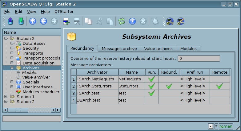
Fig. 4.6b. The "Redundancy" tab of subsystem "Archives".
The "Messages archive" tab (Fig.4.6c) contains the configuration of messages archive and the request form of messages from the archive.
Configuration of the messages archive is represented by the fields:
- Messages buffer size indicates the dimension of the area of memory reserved for the interim buffer of messages. Messages from the buffer are requested for viewing and archived with the messages archivers.
- Archiving period (s) the periodicity with which the archivers select messages from the buffer for their archiving.
The messages request form contains the configuration fields of the request and the table of results. Configuration fields of the request are:
- Time, size (s) and level specifies the request time, the size or the depth (in seconds) and the minimum level of messages (more than or equal).
- Category pattern specifies the category of the requested messages. In the category you can specify the elements of a sample of the template, namely, the characters '*' for any string and '?' for any character, as well as a regular expression enclosed between '/' (/mod_(System|LogicLev)/).
- Archivators indicates the messages archivators (separated by symbol ';'), for which the request is to be processed. If the value is missing, the request will be processed for the buffer and all archivers. If "<buffer>" is specified, then the request will be processed for the messages buffer.
The result table contains rows of messages with the following columns:
- Time message's time.
- Category message's category.
- Level message's level.
- Message message's text.
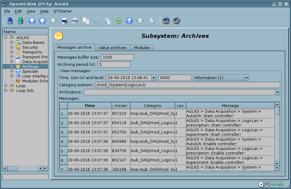
Fig. 4.6c. The "Messages archive" tab of the subsystem "Archives".
Tab "Value archives" (Fig.4.6d) contains the general configuration of value's archiving and the list of archives of values. In the context menu of the list of values the user has the opportunity to add, delete and move to the desired archive. The general configuration of archiving is represented by the fields:
- Get data period (ms) indicates the periodicity of the active archiving task. In fact, the highest level of detail or the minimum period of active archives is determined by this value.
- Get data task priority level sets the priority of task of active archiving. It is used when scheduling the operating system tasks. In the case of proper access availability this field includes the planning of the archiving task in real time and with the specified priority otherwise it modifies parameter "nice" of the task.
- Variable timestamp force to current time time-stamp of values, received on the active archivation, forces to current time, replaces the data source time.
The "Modules" tab (Fig. 4.1b) contains a list of modules in subsystem "Archives" and it is identical for all modular subsystems.
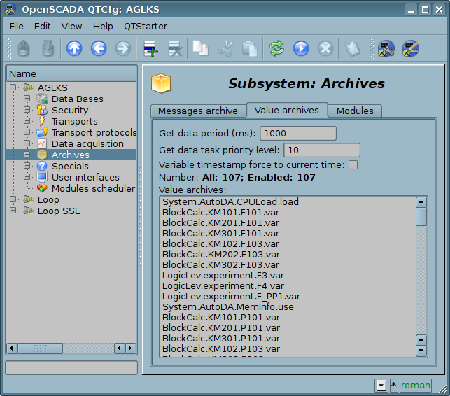
Fig. 4.6d. The "Value archives" tab of the subsystem "Archives".
Archive of values of subsystem "Archives" provides the configuration page with the tabs "Archive", "Archivators" and "Values".
Tab "Archive" (Fig.4.6e) contains the basic settings of the archive:
- Section "State" Contains the properties, which characterize the state of the archive:
- Running The state of the parameter "Running". Running archive collects data in the buffer and is served by the archivators.
- Buffer start and end Time of values begin and end into the buffer.
- Archive DB Database address for storing the archive's data.
- Section "Config" Directly contains the configuration fields:
- ID Information on the archive's identifier.
- Name Specifies the archive's name.
- Description Brief description of the archive and its purpose.
- To start Indicates the state "Running" in which to transfer the archive at startup.
- Source Indicates the type and address of the source. Type of source is indicated from the list: "Passive", "Passive param. attribute" or "Active param. attribute". Passive archive does not have an associated source of values, the data to the such archive the source transfers by itself, for example from users' calculate procedures on internal programming language. Types with the attribute of the parameter in the address field indicate the parameter of the subsystem "Data acquisition" as the source. Passive attribute of the parameter sends data to the archive by itself with its own period of data acquisition. Active attribute of the parameter is queried by the archiving task of this subsystem. Virtually all sources of real data process into passive mode of archiving as the data at once placed in the attribute parameter, sometimes by time stamp. But calculators (DAQ.JavaLikeCalc, DAQ.LogicLev, DAQ.BlockCalc) can only operate in active mode, archiving, because the data in the attribute parameter is updated only with their direct request, and are taken from the execution context. In the case of real data sources, the difference between active and passive mode of archiving by the fact that in the passive mode the source can put data into the archive by timestamp, and in active mode, the timestamp is always set to the current system time.
- Data combining mode Sets combining mode for data writing from highresolution buffer (for example, 1s) to lowresolution archivator (for example, 1min.), when into single point of the archivator placed several values from buffer (for example, 60). The modes implemented: "Moving average", "Single", "Minimum" and "Maximum".
- Value type Indicates the type of values which are stored in the archive from the list: "Boolean", "Integer", "Real", "String", "Int16", "Int32", "Int64", "Real(Float)" and "Real(Double)".
- Buffer period (s) Indicates the periodicity of values in the archive's buffer.
- Buffer size (items) Indicates the dimension and depth of the archive's buffer. The dimension is usually set in terms of 60 sec of the periodicity of the archiving task with the reserve.
- Buffer hard time grid Indicates the mode of the buffer. The hard grid mode involves the memory reservation for each value, but without the timestamp. This mode eliminates the possibility of packaging the adjacently-identical values, but also saves on storage of the timestamp. Otherwise, the buffer operates in the mode of storage the value and timestamp and supports the packaging of adjacently-identical values.
- Buffer high time resolution indicates the possibility of storing values at intervals up to 1 microsecond, differently the values can be stored at intervals up to 1 second.
- Fill pass points to a last value mostly the pass values fill by EVAL but sometime the source's data periodicity greater to the archive's one and it is normal.
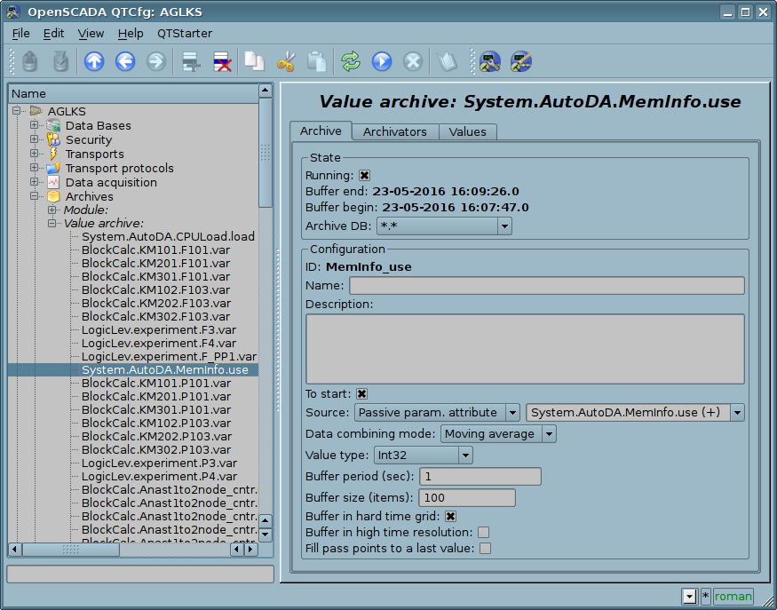
Fig. 4.6e. The main configuration tab of the values' archive of subsystem "Archives".
Tab Archivators' (Fig.4.6f) contains the table with the configuration of the processing of the archive by the available archivers. Lines are available archivers, and the columns are the following parameters:
- Archivator information on the archiver's address.
- Start information on the archiver's state "Started".
- Process sign of the processing this archive be the archiver. The field is available for modification by the user.
- Period (s) information on the periodicity of the archiver.
- Begin date and time of the archive beginning in the archiver.
- End date and time of the archive ending in the archiver.
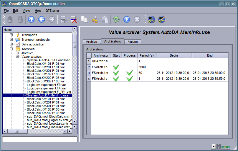
Fig. 4.6f. The "Archivators" tab of the values archive of subsystem "Archives".
Tab "Values" (Fig.4.6g) contains the values request in the archive and the result as a table of values or image of the trend. Values request contains the fields:
- Time indicates the time of request. It contains two fields: the field of date + time and microseconds.
- Size (s) specifies the size or depth of the request in seconds.
- Archivator indicates values archiver for which the request is to be processed. If the value is missing, the request will be processed for the buffer and for all archivers. If the <buffer> is specified, then the request will be processed only for the archive's buffer.
- Show trend indicates the necessity for presentation of the archive's data in the form of a graph (trend), otherwise the result is presented in a table that contains only time and value. In the case of installation of this field the schedule is formed and displayed, in addition additional configuration fields of the image settings are appeared:
- Picture size indicates the width and height of the generated image in pixels.
- Value scale indicates the lower and upper limit of the scale of value. If both values are set to 0 or equal, then the scale will be determined automatically depending on the values.
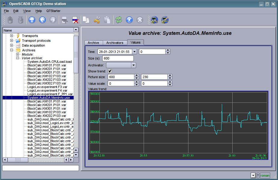
Fig. 4.6g. The "Values" tab of the values archive of subsystem "Archives".
Each module of the "Archives" subsystem provides configuration page with the tabs "Archivators" and "Module". The "Archivators" tab (Fig.4.6h) contains a list of messages and values archivers registered in the module. The context menu of the list provides user with possibility to add, delete and move to the desired controller. The "Module" tab contains information about the module of subsystem "Archives" (Fig. 4.1d), whose structure is identical for all modules.
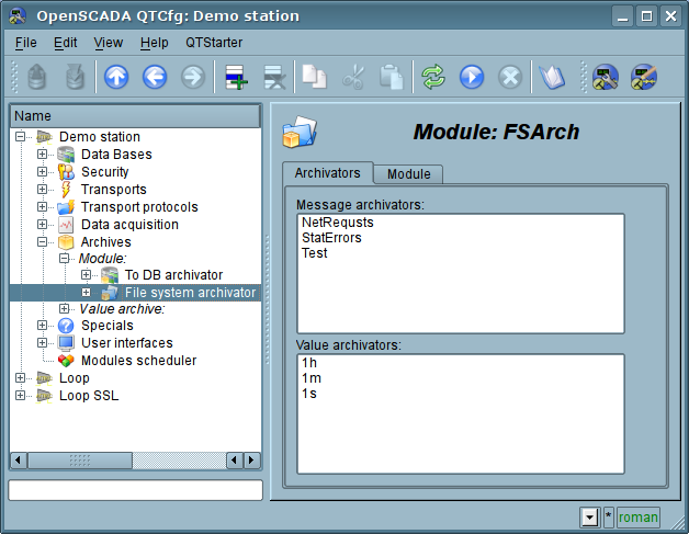
Fig. 4.6h. The "Archivators" tab of the module of subsystem "Archives".
Messages archivators contains their own configuration page with tabs "Archivator" and "Messages".
The "Archivator" tab (Fig.4.6i) contains the basic settings. The structure of these settings may differ slightly from one module of this subsystem to another as you can find in the own documentation of modules. As an example we shall examine the settings of the messages archiver from the module of the archive on the file system Arch.FSArch Settings:
- Section "State" contains the properties, hich characterize the archivers' state:
- Running archivers' state "Running". The running archiver processes the messages archive buffer and puts his data in its repository, but also it processes requests for access to data in the repository.
- Archivator DB database address for storing the archiver's data.
- End date + time of the last data in the archiver's repository.
- Begin date + time of the first data in the archiver's repository.
- Archivator files size (kB) information about the total size of the archiver's files with the data.
- Archiving time (ms) time spent on the archiving of messages archive data.
- Section "Config" directly contains the configuration fields:
- ID information on the archiver's identifier.
- Name indicates the archiver's name.
- Description brief description of the archiver and its purpose.
- To start indicates the status "Running", in which to transfer archiver at startup.
- Message categories list of categories of messages, separated by ';'. Messages matched with the templates or regular expressions of categories will be processed by the archiver. In the category you can specify the elements of a sample of the template, namely, the characters '*' for any string and '?' for any character, as well as a regular expression enclosed between '/' (/mod_ (System|LogicLev)/).
- Message level indicates the level of archiver's messages. Messages with a level greater than or equal to the specified one are processed by the archiver.
- Address address of the storage in the specific for the type of archiver (module) format. Format description usually available in the tooltip for this field. In the example it is the relative path to the storage directory.
- Section "Additional options" specialized section for module about the contents of which you can read in the documentation on the module.
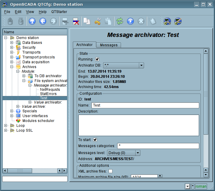
Fig. 4.6i. The main tab of the messages archiver configuration of subsystem "Archives".
The "Messages" tab (Fig.4.6j) contains the form of the messages request from the archive of the archiver:
- Time, size (s) and level specifies the request time, the size or the depth (in seconds) and the minimum level of messages (more than or equal).
- Category pattern indicates the category of the requested messages. In the category you can specify the elements of a sample of the template, namely, the characters '*' for any string and '?' for any character, as well as a regular expression enclosed between '/' (/mod_ (System|LogicLev)/).
The result table contains messages rows with the following columns:
- Time message time.
- Category message category.
- Level message level.
- Message message text.
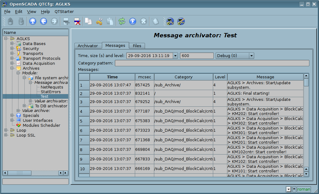
Fig. 4.6j. Tab of the messages request "Messages" of the messages archiver of subsystem "Archives".
Values archivers contains their own configuration page with tabs "Archivator" and "Archives".
The "Archivator" tab (Fig.4.6k) contains the basic settings. The structure of these settings may differ slightly from one module of this subsystem to another as you can find in the own documentation of modules. As an example we shall examine the settings of the messages archiver from the module of the archive on the file system Arch.FSArch Settings:
- Section "State" contains the properties, hich characterize the archivers' state:
- Running archivers' state "Running". The running archiver processes the messages archive buffer and puts his data in its repository, but also it processes requests for access to data in the repository.ηΰοπξρϋ νΰ δξρςσο κ δΰννϋμ β υπΰνθλθωε.
- Archiving time (ms) information about the time spent on archiving data of the archives buffers. Periodicity of archiving is set in the field "Period archiving" in the section "Config" of the tab.
- Archivator DB database address for storing the archiver's data.
- Section "Config" directly contains the configuration fields:
- ID information on the archiver's identifier.
- Name indicates the archiver's name.
- Description brief description of the archiver and its purpose.
- To start indicates the status "Running", in which to transfer archiver at startup.
- Address address of the storage in the specific for the type of archiver (module) format. Format description usually available in the tooltip for this field. In the example it is the relative path to the storage directory.
- Value period (s) indicates the periodicity of values that are contained in the archiver's repository.
- Period archiving (s) indicates the periodicity of the archives buffers data archiving task. The dimension of the archives buffers in the time expression must not be less, and preferably somewhat greater then the periodicity of the of archiving task. Set zero period for disable using the archiver for buffer processing, only for direct write.
- Selection priority selection the archiver priority for "All" sources using mode. Set to zero for full the selection disable.
- Section "Additional options" specialized section for module about the contents of which you can read in the documentation on the module.
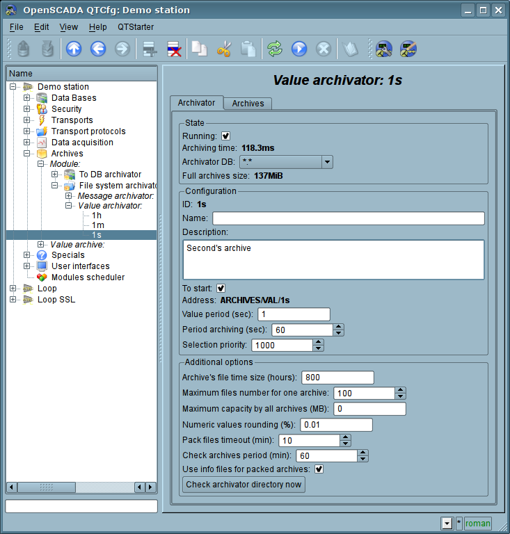
Fig. 4.6k. The main tab of the values archiver configuration of subsystem "Archives".
The "Archives" tab (Fig.4.6l) contains a table with information about the archives being processed by the archiver. In the rows the table contains archives, and in the columns the following information:
- Archive archive's name.
- Period (s) archive's periodicity in seconds.
- Buffer size buffer's dimension in units.
- Files size (Mb) specific to the module Arch.FSArch field with information about the total size of the files of the archiver's storage for the archive.
In the case of the module Arch.FSArch in this tab you can find the form of export the archiver's data.
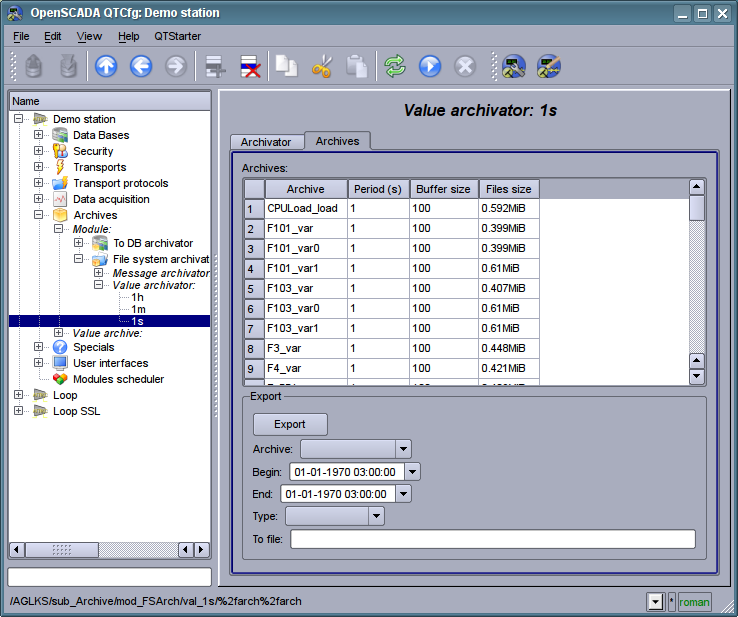
Fig. 4.6l. The "Archives" tab of the values archiver of subsystem "Archives".
4.7. Subsystem "User interfaces"
The subsystem is modular. To configure the subsystem the root page of the subsystem "User Interfaces" is provided, it contains the tab "Modules". The "Modules" tab (Fig. 4.1b) contains a list of modules of subsystem and it is identical for all modular subsystems.
Each module of the subsystem "User Interfaces" provides configuration page with the tabs "User Interface" and "Module". The "User Interface" tab (Fig.4.7a) provides the parameter for monitoring the "Running" status of the module, as well as the configuration sections specialized for the modules of this subsystem. On the "Module" tab there is an information about the module of the subsystem "User Interfaces" (Fig. 4.1d), which structure is identical for all modules.
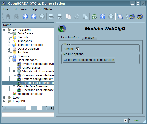
Fig. 4.7a. The "User Interface" tab of the module of subsystem "User Interfaces".
4.8. Subsystem "Specials"
The subsystem is modular. To configure the subsystem the root page of the subsystem "User Interfaces" is provided, it contains the tab "Modules". The "Modules" tab (Fig. 4.1b) contains a list of modules of subsystem and it is identical for all modular subsystems.
Each module of the subsystem "Specials" provides configuration page with the tabs "Special" and "Module". The "Special" tab (Fig.4.8a) provides the parameter for monitoring the "Running" status of the module, as well as the configuration sections specialized for the modules of this subsystem. On the "Module" tab there is an information about the module of the subsystem "Specials" (Fig. 4.1d), which structure is identical for all modules.
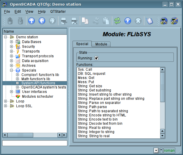
Fig. 4.8a. The "Special" tab of the module of subsystems "Specials".
4.9. Subsystem "Modules scheduler"
The subsystem is not modular. To configure the subsystem the subsystem's page "Modules scheduler" is provided, it contains tab "Subsystem". The "Subsystem" tab (Fig.4.9a) contains the basic settings of the subsystem. The structure of the tab "Subsystem":
- Path to shared libs (modules) information about the location of the directory with the modules of the OpenSCADA system. It is set by the parameter <ModDir> of the station, of the configuration file.
- Denied modules the list, separated by ';' of modules that are denied for automatically connection and updating. It is set by the parameter <ModDeny> of the section of subsystem "sub_ModSched" of station of configuration file. List of denied modules has higher priority than allowed.
- Allowed modules the list, separated by ',', of modules that are authorized for automatic connection and renewal. The value of '*' is used to resolve all the modules. It is set by the parameter <ModAllow> of the section of subsystem, sub_ModSched, of the station of the configuration file.
- Check modules period (sec) indicates the periodicity of testing modules on the fact of their updating. Modules that are allowed for automatically connection and updating will be automatically updated.
- Check modules now command to check the modules on the fact of their updating. Modules that are allowed for automatically connection and updating will be automatically updated.
- Shared libs (modules) table with the list of shared libraries with the modules detected by OpenSCADA. Rows are modules, and in the columns there is an information about them:
- Path information on the full path to the shared library.
- Time information about the time the of last modification of a shared library.
- Modules information about the list of modules in a shared library.
- Enable state "Enable" of the shared library. Privileged users are provided with an opportunity to manually enable/disable the shared libraries by changing this field.
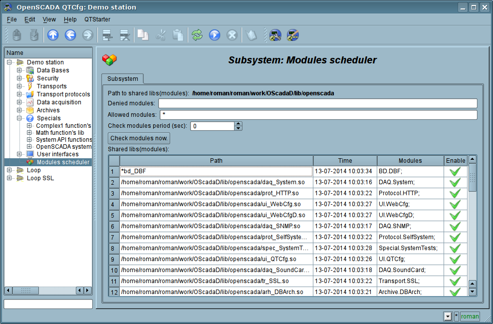
Fig. 4.9a. The main configuration tab of subsystem "Modules scheduler".
Action source page doesn't exist yet(/Home Page En / Doc / Programm Manual / part 4 / part 10?)