Dynamic model of the Anastasievskaja GLKS in real time
| Name: ModelAGLKS Founded: January 2006 Members: Roman Savochenko, Maxim Lysenko Description: The project is devoted to the creation of the full dynamic model of real-time of Anastasievskaja GLKS. Address: Current DB into the Live execution: | 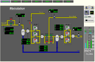 |
Introduction
Anastasievskaya GLKS (AGLKS) is the technological process designed for two-stage gas compression of gas fields. For this purpose GLKS is provided with six centrifugal compressors: three compressor for low and high pressure part, thus providing redundancy and allowing the parallel operation.
To test the control algorithms of GLKS, especially anti surging algorithms the creation of mathematical model of GLKS was required. The model must run on the single board computer with the PCI and communicate with the controller of the technological process control. For development of the model it was used library of technological devices of OpenSCADA. Subsequently, the TP model of the compressor station has grown into an autonomous system which is used in the OpenSCADA project as the demonstration of features and capabilities.
1 Technological process
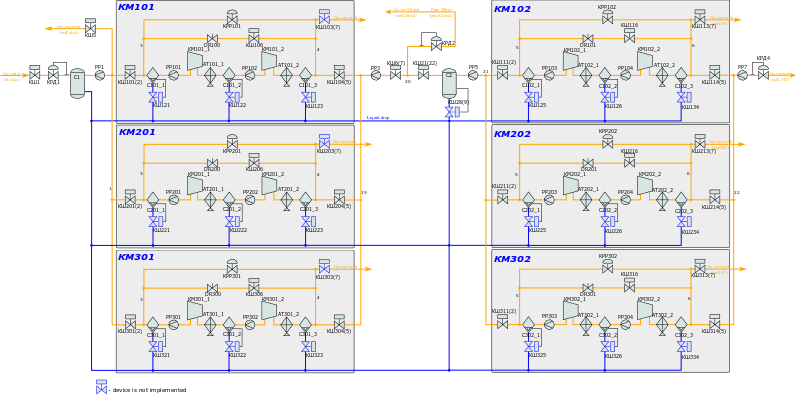
Before creating the GLKS model, it was created the principle circuit of the model of technological process, based on the principle circuit of the real process. The resulting scheme is shown in Figure 1.
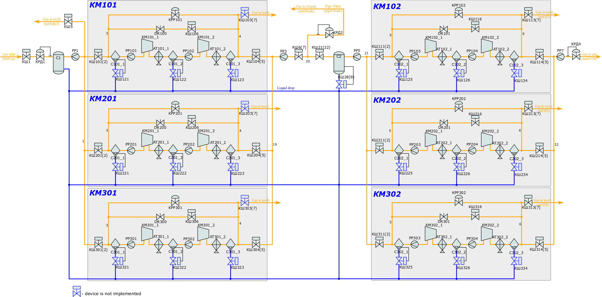
Figure 1. Principle scheme of the AGLKS model.
2 Modeling
To construct the model of technological process on the basis of the available models of tech. devices it was directly used the source principle scheme and block calculator (BlockCalc) of the OpenSCADA system. The technological devices added to the block scheme in accordance to the principle scheme. Several blocks were added as the accessory ones and for the nodes of the flows. The numbers of the nodes' blocks are indicated on the principle scheme near the flows nodes.
The model is implemented as an eight-block schemes of the block calculator. Structure and properties of block schemes are shown in Table 1.
Table 1. Model block scheme
| ID | Name | Purpose | Period of execution (ms) | Execution time for Athlon 64 3000+ (ms) |
| gen | Mainstation | Contains the model of general part of the compressor station, namely, all that is shown on the principle scheme outside of the gray blocks of individual compressors. | 10 | 0.52 |
| gen_cntr | Mainstation (controller) | Contains the model of the control system of the mainstation part | 1000 | 0.033 |
| KM101 | The model of КМ101 | Contains the model of the first compressor KМ101 of low pressure. | 10 | 0.3 |
| KM102 | The model of КМ102 | Contains the model of the first compressor KМ102 of high pressure. | 10 | 0.35 |
| KM201 | The model of КМ201 | Contains the model of the second compressor KМ201 of low pressure. | 10 | 0.3 |
| KM202 | The model of КМ202 | Contains the model of the second compressor KМ202 of high pressure. | 10 | 0.35 |
| KM301 | The model of КМ301 | Contains the model of the third compressor KМ301 of low pressure. | 10 | 0.3 |
| KM302 | The model of КМ302 | Contains the model of the third compressor KМ302 of high pressure. | 10 | 0.35 |
From the characteristics of block schemes can be seen that the capacity of the model as a whole to the CPU Athlon 64 3000+ (2000MHz) is 19.5%.
Table 2. lists the models being used in accordance with the principle scheme.
Table 2. Using of the technological devices model
| Technological device model | Technological devices (blocks of the model) |
| Ball crane (ballCrane) | gen.КШ1им, gen.КШ2им, gen.КШ5им, gen.КШ7им, gen.КШ21им, gen.КШ22им, KM*01.КШ101им, KM*01.КШ102им, KM*01.КШ104им, KM*01.КШ105им, KM*01.КШ106им, KM*02.КШ111им, KM*02.КШ112им, KM*02.КШ114им, KM*02.КШ115им, KM*02.КШ116им |
| Gas compressor (compressor) | KM*01.KM101_1, KM*01.KM101_2, KM*02.KM102_1, KM*02.KM102_2 |
| Air cooler (cooler) | KM*01.AT101_1, KM*01.AT101_2, KM*02.AT102_1, KM*02.AT102_2 |
| Diaphragm (diafragma) | gen.PP1, gen.PP3, gen.PP5, gen.PP7, KM*01.PP101, KM*01.PP102, KM*02.PP103, KM*02.PP104 |
| Valve (klap) | gen.КШ1, gen.КШ5, gen.КШ6, gen.КШ21, KM*01.KPP101, KM*01.DR100, KM*01.КШ101, KM*01.КШ104, KM*01.КШ106, KM*02.KPP102, KM*02.DR101, KM*02.КШ111, KM*02.ЛКШ113, KM*02.КШ114, KM*02.КШ116 |
| Lag (lag) | gen.P_КРД2 |
| Network (loading) (net) | gen.netGVD, gen.netGlinsk, gen.netFakel, KM*02.net102 |
| Pipe 1->1 (pipe1_1) | gen.pipeGlinsk |
| Pipe 1->2 (pipe1_2) | gen.node1, gen.node20 |
| Pipe 1->3 (pipe1_3) | gen.node1_1, gen.node21, KM*01.node4_1 |
| Pipe 1->4 (pipe1_4) | KM*02.node6_1 |
| Pipe 3->1 (pipe3_1) | gen.node22, gen.node19, KM*01.node3_1, KM*02.node5_1 |
| Noise (2 harmonic + rand) (noise) | gen.noisePP3 |
| Separator (separator) | gen.C1, gen.C2, KM*01.C101_1, KM*01.C101_2, KM*01.C101_3, KM*02.С102_1, KM*02.С102_2, KM*02.С102_3 |
| Source (pressure) (src_press) | gen.SrcGas |
Through the using of the library of the models of tech. devices and concepts for building the dynamic models it has been obtained the dynamic model, from which you can get the parameters at any point of the principle scheme as for the study and for testing of the control algorithms.
In the model of the control system of the mainstation part there are three PID: PC_KRD1, PC_KRD2 and PC_KRD3 to regulate the pressure at the input of the CS, between the compressors of low and high pressure, as well as at the output of the CS.
To obtain the information on the technological process the parameters of TP (Table 3) were created, which represent data from individual nodes of the model.
Table 3. Parameters of the technological process
| Сode | Description | Properties | Source |
| Mainstation controller BlockCalc.gen | |||
| F2, F_PP1 | Gas flow through the diaphragm PP1 | PP1.Fi | |
| F3 | The gas flow through a pipe to Glinsk | pipeGlinsk.Fi | |
| F4, F_PP5, F5_6 | Gas flow through the diaphragm PP5 | PP5.Fi | |
| F7_8 | Gas flow through the diaphragm PP7 | PP7.Fi | |
| F_PP3 | Gas flow through the diaphragm PP3 | PP3.Fo | |
| KSH1 | The control block of the ball valve KSH1 | КШ1им.com, КШ1им.st_open, КШ1им.st_close | |
| KSH2 | The control block of the ball valve KSH2 | КШ2им.com, КШ2им.st_open, КШ2им.st_close | |
| KSH5 | The control block of the ball valve KSH5 | КШ5им.com, КШ5им.st_open, КШ5им.st_close | |
| KSH6 | The control block of the ball valve KSH6 | КШ6им.com, КШ6им.st_open, КШ6им.st_close | |
| KSH7 | The control block of the ball valve KSH7 | КШ7им.com, КШ7им.st_open, КШ7им.st_close | |
| KSH21 | The control block of the ball valve KSH21 | КШ21им.com, КШ21им.st_open, КШ21им.st_close | |
| KSH22 | The control block of the ball valve KSH22 | КШ22им.com, КШ22им.st_open, КШ22им.st_close | |
| L1 | The liquid level in the separator C2 | C2.Lж | |
| Ti | The gas temperature at the input of the CS. | КШ1.Ti | |
| T_PP1 | The gas temperature at the diaphragm PP1 | КРД1.To | |
| T_PP3 | The gas temperature at the diaphragm PP3 | node19.To | |
| T_PP5 | The gas temperature at the diaphragm PP5 | КШ21.To | |
| Pi | The gas pressure at the input of the CS. | КШ1.Pi | |
| P_PP1 | Gas pressure at the diaphragm PP1 | PP1.Po | |
| P_PP3, PC0601 | Gas pressure at the diaphragm PP3 | PP3.Po | |
| P_PP5, P4, PT0404 | Gas pressure at the diaphragm PP5 | PP5.Po | |
| PT0804, P3 | The gas pressure in the pipe to Glinsk | pipeGlinsk.Pi | |
| PT1606, PT0503 | The gas pressure in the separator С1 | C1.Po | |
| PT0406 | Gas pressure at the diaphragm PP7 | PP7.Po | |
| PT0605 | The gas pressure before control valve KRD1 | КРД1.Pi | |
| Virtual controller of the mainstation LogicLev.experiment | |||
| F3 | The gas flow through a pipe to Glinsk | Template: base.simleBoard t/h, (0;100), a(10;90), w(35;80) | BlockCalc.Anast1to2node.F3.var |
| F4, F_PP5 | Gas flow through the diaphragm PP5 | Template: base.simleBoard t/h, (0;100), a(10;90), w(35;80) | BlockCalc.Anast1to2node.F4.var, BlockCalc.Anast1to2node.F_PP5.var |
| F_PP1 | Gas flow through the diaphragm PP1 | Template: base.simleBoard t/h, (0;150) | BlockCalc.Anast1to2node.F_PP1.var |
| F_PP3 | Gas flow through the diaphragm PP3 | Template: base.simleBoard t/h, (0;150) | BlockCalc.Anast1to2node.F_PP3.var |
| Ti | The gas temperature at the input of the CS. | Template: base.simleBoard deg. С, (-50;50), a(-20;40), w(-10;30) | BlockCalc.Anast1to2node.Ti.var |
| T_PP1 | The gas temperature at the diaphragm PP1 | Template: base.simleBoard deg. С, (0;50) | BlockCalc.Anast1to2node.T_PP1.var |
| T_PP3 | The gas temperature at the diaphragm PP3 | Template: base.simleBoard deg. С, (0;50) | BlockCalc.Anast1to2node.T_PP3.var |
| T_PP5 | The gas temperature at the diaphragm PP5 | Template: base.simleBoard deg. С, (0;50) | BlockCalc.Anast1to2node.T_PP5.var |
| Pi | The gas pressure at the input of the CS. | Template: base.simleBoard kgf/cm2, (0;20), a(4;15), w(5;10) | BlockCalc.Anast1to2node.Pi.var |
| P3 | The gas pressure in the pipe to Glinsk | Template: base.simleBoard kgf/cm2, (0;100), a(10;90), w(20;80) | BlockCalc.Anast1to2node.P3.var |
| P_PP1 | Gas pressure at the diaphragm PP1 | Template: base.simleBoard kgf/cm2, (0;10) | BlockCalc.Anast1to2node.P_PP1.var |
| P_PP3 | Gas pressure at the diaphragm PP3 | Template: base.simleBoard kgf/cm2, (0;50) | BlockCalc.Anast1to2node.P_PP3.var |
| P_PP5, P4 | Gas pressure at the diaphragm PP5 | Template: base.simleBoard kgf/cm2, (0;50) | BlockCalc.Anast1to2node.P_PP5.var, BlockCalc.Anast1to2node.P4.var |
| PT0503 | The gas pressure in the separator С1 | Template: base.simleBoard kgf/cm2, (0;10), a(2;8), w(3;7) | BlockCalc.Anast1to2node.PT0503.var |
| KSH6close | Alarm for closing the valve KSH6 | Template: base.digAlarm | BlockCalc.Anast1to2node.КШ6.st_open |
| gN1 | Account node 1 | Template: base.gasPoint | |
| KSH7 | The control block of the ball valve KSH7 | Template: base.digitBlock t=5s | BlockCalc.Anast1to2node.КШ7.com, BlockCalc.Anast1to2node.КШ7.st_open, BlockCalc.Anast1to2node.КШ7.st_close |
| The BlockCalc.gen_cntr controller | |||
| PC_KRD1 | The pressure regulator at the input of the CS. | at, (0;10) | PCKRD1.* |
| PC_KRD2 | The pressure regulator between the compressors of low and high pressure. | at, (0;50) | PC_КРД2.* |
| PC_KRD3 | Regulator of the pressure at the output of CS. | at, (0;120) | PC_КРД3.* |
| The BlockCalc.KM*01 controller | |||
| KPP101 | Antistall control valve of the compressor | %, (0;100), 0 digits | KPP101.l_kl1 |
| FN101 | Flow at the output of compressor | КШ104.Fi | |
| F101 | Flow on the diaphragm PP101 | t/h, (0;100), 1 digit | PP101.Fi |
| F102 | Flow on the diaphragm PP102 | t/h, (0;100), 1 digit | PP102.Fi |
| TE1202_1 | Temperature after the first stage of the compressor | K, (273;373), 0 digit | КМ101_1.To |
| TE1205_1 | Temperature after the second stage of the compressor | K, (273;433), 0 digit | КМ101_2.To |
| TE1313_1 | The temperature at the input of the first stage of the compressor | K, (273;373), 0 digit | node3_1.To |
| TE1314_1 | The temperature after the fridge of the first stage of the compressor | K, (273;373), 0 digit | AT101_1.To |
| TE1206_1 | The temperature after the fridge of the second stage of the compressor | K, (273;373), 0 digit | AT101_2.To |
| AT101_1 | Control block of the fridge after the first stage of the compressor | AT101_1.Ti, AT101_1.To, AT101_1.Wc | |
| AT101_2 | Control block of the fridge after the second stage of the compressor | AT101_2.Ti, AT101_2.To, AT101_2.Wc | |
| KSH101 | The control block of the ball valve KSH101 | КШ101им.com, КШ101им.st_open, КШ101им.st_close | |
| KSH102 | The control block of the ball valve KSH102 | КШ102им.com, КШ102им.st_open, КШ102им.st_close | |
| KSH104 | The control block of the ball valve KSH104 | КШ104им.com, КШ104им.st_open, КШ104им.st_close | |
| KSH105 | The control block of the ball valve KSH105 | КШ105им.com, КШ105им.st_open, КШ105им.st_close | |
| KSH106 | The control block of the ball valve KSH106 | КШ106им.com, КШ106им.st_open, КШ106им.st_close | |
| PT0202_1 | Pressure after the first stage of the compressor | at, (0;20), 1 digit | КМ101_1.Po |
| PT0204_1 | Pressure after the second stage of the compressor | at, (0;50), 1 digit | КМ101_2.Po |
| PT1006_1 | Pressure on the diaphragm PP102 | at, (0;20), 1 digit | PP102.Pi |
| P101 | Pressure on the diaphragm PP101 | at, (0;10), 1 digit | PP101.Pi |
| ST8612_1 | Rotation speed of the compressor | 1000x rpm, (0;10), 2 digits | КМ101_1.N |
| BlockCalc.KM*02 controller | |||
| KPP102 | Antistall control valve of the compressor | %, (0;100), 0 digits | KPP102.l_kl1 |
| TE1202_4 | Temperature after the first stage of the compressor | K, (273;373), 0 digit | KM102_1.To |
| TE1205_4 | Temperature after the second stage of the compressor | K, (273;433), 0 digit | KM102_2.To |
| TE1313_4 | The temperature at the input of the first stage of the compressor | K, (273;373), 0 digit | node5_1.To |
| TE1314_4 | The temperature after the fridge of the first stage of the compressor | K, (273;373), 0 digit | AT102_1.To |
| TE1206_4 | The temperature after the fridge of the second stage of the compressor | K, (273;373), 0 digit | AT102_2.To |
| F103 | Flow on the diaphragm PP103 | t/h, (0;100), 1 digit | PP103.Fi |
| F104 | Flow on the diaphragm PP104 | t/h, (0;100), 1 digit | PP104.Fi |
| PT0202_4 | Pressure after the first stage of the compressor | at, (0;75), 1 знак | KM102_1.Po |
| PT0204_4 | Pressure after the second stage of the compressor | at, (0;150), 1 знак | KM102_2.Po |
| PT1006_4 | Pressure on the diaphragm PP104 | at, (0;75), 1 digit | PP104.Pi |
| P103 | Pressure on the diaphragm PP103 | at, (0;50), 1 digit | PP103.Pi |
| KSH111 | The control block of the ball valve KSH111 | КШ111им.com, КШ111им.st_open, КШ111им.st_close | |
| KSH112 | The control block of the ball valve KSH112 | КШ112им.com, КШ112им.st_open, КШ112им.st_close | |
| KSH114 | The control block of the ball valve KSH114 | КШ114им.com, КШ114им.st_open, КШ114им.st_close | |
| KSH115 | The control block of the ball valve KSH115 | КШ115им.com, КШ115им.st_open, КШ115им.st_close | |
| KSH116 | The control block of the ball valve KSH116 | КШ116им.com, КШ116им.st_open, КШ116им.st_close | |
| ST8612_4 | Rotation speed of the compressor | 1000x rpm, (0;15), 2 digits | KM102_1.N |
3 User interface
User interface of the model is represented by seven signaling objects (Fig. 2). Six of them contain frames of the compressors KM101, KM201, KM301, KM102, KM202 and KM302. The seventh is common for the entire compressor station and contains mainstation frames. Mainsttion signaling group includes two mnemonic scheme, two groups of graphs, a group of contours, an overview frame and five documents.
")
Fig.2. General view of the user interface window.
The mnemonic schemes of the signaling object "Mainstation" are resented in Figure 3 and Figure 4.
")
Fig.3. The main mnemonic scheme of CS
")
Fig.4. Test mnemonic scheme
Graphics groups "Mass flows" and "Temperatures" are presented at Fig.5 and Fig.6 respectively.
")
Fig.5. Graphics group "Mass flows"
")
Fig.6. Graphics group "Temperatures"
Contours group "Test group" (Fig. 7) contains the contours of all the regulators and a set of important parameters.
")
Fig.7. Contours group "Test group".
Group of the overview frames "Overview 1"(Fig. 8) contains the frames of main parameters.
")
Fig.8. Group of the overview frames "Overview 1".
The documents "Table of accumulation instantaneous values", "Log of interruptions", "Table of average over hour values", "Table of average over day values" and "Day Report" are presented in Fig.9, Fig.10, Fig.11, Fig.12 and Fig.13 respectively.
")
Fig.9. The document "Table of accumulation instantaneous values".
")
Fig.10. The document "Log of interruptions".
")
Fig.11. The document "Table of average over hour values".
")
Fig.12. The document "Table of average over day values".
")
Fig.13. The document "Day Report".
Signaling objects of the compressors of low pressure contain mnemonic scheme (Fig.14) and graphics group (Fig.15).
")
Fig.14. Mnemonic scheme of the low pressure compressor.
")
Рис.15. Graphics group of the low pressure compressor
Signaling objects of the high pressure compressors include mnemonic scheme (Fig.16) and graphics group (Fig.17).
")
Fig.16. Mnemonic scheme of the high pressure compressor.
")
Fig.17. Graphics group of the high pressure compressor
To display the dynamics of the entire compressor station the result graphics are provided (Fig.18)
")
Fig.18. The result graphics "Page 1".
4 Results
The result of the development is the complete dynamic model of technological process of the compressor station. This model is available in three languages and is included in the distributions of OpenSCADA as the demonstration of features and capabilities.
The model provides for the availability to control the TP on behalf of the operator, including the following operation:
- control the pressure regulators:
- regulator's mode change: "Automatic" or "Manual";
- setting the desired values of set point or manual output of the control mechanism;
- tuning the PID parameters.
- gate valves and ball valves control through the control panel and the shortcut menu by closing or opening;
- manual input of the values of rotations (ST8612) and the positions of the antistall valves (KPPx0x).
The model was successfully applied for debugging algorithms of antistall protection of the compressors of Anastasievskaja GLKS.
Resource intensity of the model was 70% on the core processor 800 MHz.
Links
 model_sh.png