Quick start
Authors: Roman Savochenko, Maxim Lysenko (2010-2012)State: Publication
Video-addon:
Introduction
The OpenSCADA is extremely modular, flexible and multi-functional SCADA-system. As a consequence of this the first contact with OpenSCADA can be quite complex because of the small chance of matching the previous experience of the user or complete lack of it with the methods of work in OpenSCADA. However, this is largely just a first impression, because the whole power of OpenSCADA is in the palm of the user, because of the abundance of which the user can get confused, and he may require considerable efforts to select the necessary functions to solve his tasks.For this reason, and to visualize the general concept of work in OpenSCADA this document is created. The document in the concise and understandable form shows the path from start of OpenSCADA to creation of the user interface elements on real examples. In addition, the document contains the chapter with recipes for the configuration, implementation, and typical problems of the user.
The document does not contain the detailed description of the concept and a deep dive into the details of OpenSCADA, and provides links to the appropriate OpenSCADA documents, containing such information.
Document description is synchronized with the implementation of the examples on the demonstration database (DB), AGLKS model. Consequently, the user must obtain the distribution kit of OpenSCADA with this database for illustrative study and testing the examples.
1. Terms, definitions and abbreviations
The automated workplace Usually consists of a system unit of the computer system, display, mouse, sometimes with the keyboard, and other peripheral equipment that is used for visual representation of technological process data and making the control actions on the TP.Lock (term) notional boundary of technological parameter, in the case of its getting over the preset algorithm steps to prevent the accident are made. In some modes of TP (start) in accordance with the regulation it may be necessary to disable the lock (unlocking).
Unlocking (term) process of the lock disabling for the duration of the TP working in the modes for which the regulation provides this operation. Attention, unlocking the technological parameters is strict accountable operation and the must be made by operational staff in the proper order.
Quittance (term) the process of confirming the fact that operational staff drew attention to the failures of TP working. This process usually entails the adoption of measures by the operator to correct violations and pressing the appropriate button to stop the alarm.
PLC (abbreviation) Industrial PLC. Microprocessor-based electronic device to which via computer-process interface (CPI) the signal of processing parameters are going. PLC acts the role of the direct data acquisition, processing and making the control actions by means of algorithms of automatic control. In addition the PLC provides data for the visualization of TP, and receives data of the manual intervention from the "top level" system.
Alarm (term) process of notifying the operational staff of the violation of process or work of the automation equipment. Way of signaling may be of different types of impacts on human senses in order to attract attention. Often it is involved the following types of alarms:
- Light alarm usually is done by changing the color of the graphic object (blinking) to emerging events and by the setting of static accidents colors (red and yellow) for acknowledged events.
- Sound is made by an audible signal at the time of occurrence of the event. Type of alarm can be monotonous and the synthesized voice message with information about the violation.
TP (abbreviation) Technological process. The whole complex of technological equipment of the production process.
CPI (abbreviation) Computer-Process Interface. A number of devices or modules of PLC, to which are directly connected the signals from the sensors of TP for subsequent conversion from analog to digital form and vice versa. The transformation is carried out with aim of further processing of values of technological parameters in the PLC.
Alarm setpoint (term) conventional boundary of the value of technological parameter, the overcoming of which is considered ad the emergency situation. Usually the following boundaries are provided:
- The upper and lower emergency boundaries boundaries of the emergency values of technological parameter.
- The upper and lower warning boundaries boundaries of the prevention, regulation boundaries, of the violation of the technological parameter of the working range.
- Failure sign of parameter getting over the hardware boundaries of technological equipment. Usually it characterizes the sensor failure, breakage of the communication channel with the sensor or PLC.
SCADA (abbreviation) Supervisory Control And Data Acquisition. The software that performs complex tasks of data acquisition of TP, their archiving and presentation, as well as the making the control actions by the operator in manual mode.
2. Installation
The installation of OpenSCADA distribution kit can be done in two ways. The first and the easiest way is to get packages for your Linux distribution. The second to build the OpenSCADA system from sources. In general, the installation procedure depends strongly on the used Linux distribution and it does not seem possible to exhaustively describe it in this guide! Therefore, you may need a deep familiarity with the mechanisms of software installation for the selected Linux distribution from its documentation.If user does not have deep enough knowledges and skills in the chosen Linux distribution, it is strongly recommended to choose the Linux distribution by the criterion of existence for it the packages of OpenSCADA in the repositories of the distribution, which will ensure an easy and problem-free installation!
If the user can not only install the OpenSCADA, but also the Linux distribution, for the first time he can use the "live" distribution of Linux, with the installed and ready for work or study demonstration of OpenSCADA. Currently are available "live" builds on the basis of Debian and ALTLinux distribution in the form of the hybrid CD-images on the page:
2.1. Installing OpenSCADA from packages
Installing OpenSCADA from packages, in its turn, can be made by two methods. The first the simplest one, when packages of OpenSCADA are already present in the official, additional repositories of the used Linux distribution or self repositories of OpenSCADA. Installation of that packages the question of running the typical program of packages' management followed by selection of the OpenSCADA packages. The second method is when the OpenSCADA packages are got and installed manually.To check for OpenSCADA packages presence in the repositories of the used Linux distribution, as well as to download OpenSCADA packages for manual installation you can at download page of the official OpenSCADA site (
2.1.1. The repository packages appending and installing OpenSCADA from it
At the moment the OpenSCADA packages can be found in the repositories of such OS Linux distributions:The repositories addresses you can get on same downloading OpenSCADA page (
If you are installing from the repository you should only select the package "openscada-Model.AGLKS". Everything else, according to the dependencies, will be selected and installed automatically.
Setting from a repository simply but it is specific for each Linux distributive, window manager or concrete program of the repositories and the packages manage then for them we'll refer the reader to the documentation of the appropriate distribution or program. Her in brief let observe the repositories appending and OpenSCADA installing with typical command line tools aid:
The packages repositories based on manager APT (Debian, Ubuntu, ALTLinux) appending by edition file /etc/apt/sources.list and one line inserting:
Debian: "deb ftp://ftp.oscada.org/OpenSCADA/0.8.0/Debian/8 ./"
Debian (Work version): "deb ftp://ftp.oscada.org/OpenSCADA/Work/Debian/8 ./"
Debian (Work version, modules separated): "deb ftp://ftp.oscada.org/Debian/8/openscada ./"
Ubuntu: "deb ftp://ftp.oscada.org/OpenSCADA/0.8.0/Ubuntu/14.04 ./"
Ubuntu (Work version): "deb ftp://ftp.oscada.org/OpenSCADA/Work/Ubuntu/14.04 ./"
Installing:
ALTLinux: "rpm ftp://ftp.oscada.org/OpenSCADA/0.8.0/ALTLinux/7 openscada main"
ALTLinux (Work version): "rpm ftp://ftp.oscada.org/OpenSCADA/Work/ALTLinux/6 openscada main"
ALTLinux (Work version, modules separated): "rpm ftp://ftp.oscada.org/ALTLinux/7 openscada main"
Installing:
Appending the key to check the sign (the authenticity) of the repository and the packages into it (not necessary and uses for not all the repositories):
The packages repositories based on manager YUM (RedHat, Fedora, CentOs) appending by the file /etc/yum.repos.d/openscada.repo creation with content:
Installing:
The packages repositories SuSE YaST appending by the command:
Installing:
2.1.2. OpenSCADA packages manual installing
For the manually installation of OpenSCADA packages lets download them from the official website or from the other source. You can download packages of two sets.The first set is represented by the nine packages:
- openscada package with all necessary files to start OpenSCADA, including all modules;
- openscada-LibDB.Main main OpenSCADA libraries for DAQ and others in the SQLite DB;
- openscada-LibDB.VCA visual components libraries in the SQLite DB;
- openscada-Model.AGLKS model "AGLKS" data bases and config (Demo: EN,RU,UK);
- openscada-Model.Boiler model "Boiler" data bases and config (EN,RU,UK);
- openscada-docEN documentation on the OpenSCADA system - English;
- openscada-docRU documentation on the OpenSCADA system - Russian;
- openscada-docUK documentation on the OpenSCADA system - Ukrainian;
- openscada-devel development packages for the creation of the separate modules for the OpenSCADA.
The second set is represented by about fifty packages with separation of OpenSCADA modules in different packages:
- openscada-core contains the OpenSCADA core, basic configuration and launching(starting) files;
- openscada-DB.* "DB" subsystem's modules;
- openscada-DAQ.* "Data acquisition" subsystem's modules;
- openscada-Archive.* "Archives" subsystem's modules;
- openscada-Transport.* "Transports" subsystem's modules;
- openscada-Protocol.* "Transport protocols" subsystem's modules;
- openscada-UI.* "User interfaces" subsystem's modules;
- openscada-Special.* "Specials" subsystem's modules;
- openscada-LibDB.Main main OpenSCADA libraries for DAQ and other into SQLite DB;
- openscada-LibDB.VCA visual components libraries into SQLite DB;
- openscada-Model.AGLKS model "AGLKS" data bases and config (Demo: EN,RU,UK);
- openscada-Model.Boiler model "Boiler" data bases and config (EN,RU,UK);
- openscada-docEN documentation on the OpenSCADA system - English;
- openscada-docRU documentation on the OpenSCADA system - Russian;
- openscada-docUK documentation on the OpenSCADA system - Ukrainian;
- openscada-devel development packages for the creation of the separate modules to the OpenSCADA.
- openscada virtual package containing dependencies for installing the typical configuration of the OpenSCADA;
- openscada-plc virtual package containing dependencies for installing the typical configuration of the OpenSCADA as a PLC;
- openscada-server virtual package containing dependencies for installing the typical configuration of OpenSCADA as a SCADA-server;
- openscada-visStation virtual package containing dependencies for installing the typical configuration of OpenSCADA as a visual SCADA-station.
The first packages' set is most provided for easy, manual installation, because it contains only nine packages. The second set is designed to be placed in a repository of Linux distribution and for the following installation of them using the packages manager, which the auto-dependency resolution. The second type of the packages' set allows you to install only the required components of OpenSCADA, thereby optimizing the working environment, which is do not allowed by the packages of the first set.
Manual installation of RPM-packages of the first set can be made by the following command, after changing the working directory to the directory with the package:
# rpm -i openscada-LibDB.Main-0.8.0-alt1.noarch.rpm openscada-LibDB.VCA-0.8.0-alt1.noarch.rpm openscada-Model.AGLKS-0.8.0-alt1.i586.rpm openscada-0.8.0-alt1.i586.rpm
Manual installation of DEB-packages of the first set is made by the following command, previously having changed the working directory to the directory with the package:
# dpkg -i openscada-libdb.main_0.8.0-1_all.deb openscada-libdb.vca_0.8.0-1_all.deb openscada-model.aglks_0.8.0-1_all openscada_0.8.0-1_i386.deb
In the process of installation it may cause bugs related to missing dependencies, because of the unresolved dependences. The manual installation of the packages means that you'll solve them manually, like installing packages of OpenSCADA, or via the packages manager of Linux distribution. You can read the details of the RPM-package software installing process by the click on:
Into Linux systems which include APT-manager of packages you can simple update downloaded files direct from the folder, do not include its to the packages repository and with automatic dependents resolving:
2.2. Installation from sources
If you can not get packages of OpenSCADA for the selected distribution, it remains the only option of OpenSCADA building from the sources. The building process of OpenSCADA is described in details in the guide on the following link http://wiki.oscada.org/HomePageEn/Doc/BuildFromSource. However, it must be noted that if you managed to build OpenSCADA from sources, then this document is not for you, and you probably can easily master the basic documents of OpenSCADA (http://wiki.oscada.org/HomePageEn/Doc/ProgrammManual).This chapter is given here for completeness and integrity of the consideration of the question, because the required qualification level of the user for this chapter is much higher than the level of the document at whole!
3. Initial configuration and start
After successful installation of the OpenSCADA with the database of "AGLKS" model no pre-configuration is required. If you want to perform a particular configuration, which differs from the base, then use the document of description the OpenSCADA program on the link: http://wiki.oscada.org/HomePageEn/Doc/ProgrammManual#h932-1.You can execute the OpenSCADA with "AGLKS" model database from the menu of the desktop environment in the "Graphics" section, "Model 'AGLKS' on open SCADA system" with the characteristic icon (Fig. 3.1).
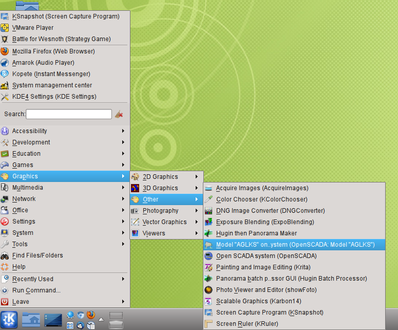
Fig. 3.1. Menu item of the desktop environment to start the demonstration of OpenSCADA.
Start also can be done from the console by the command:
After start we'll get the window of the OpenSCADA graphical configurator QTCfg (Fig.3.2) with the opened root page. Demo database specifically configured so that the first window you'll see after start it is the configurator's window. You can then open the window for creating graphical user interfaces, as well as run the user interface project's execution.
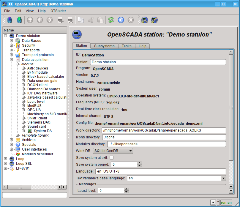
Fig. 3.2. OpenSCADA configurator - QTCfg, the root page.
Configurator of OpenSCADA is the main and sufficient instrument for the configuration of any system's component. Like many other components of OpenSCADA, configurator is implemented as a module. Besides the QTCfg configurator there may be available other configurators that performs the same function, but implemented on the basis of other technologies. For example, these are the Web-configurators: WebCfg and WebCfgD.
All actions in the future, we will make only in the configuration tool QTCfg, although all of them can be done in other configurators.
The structure of the configurator's window interface can be considered in detail by reference http://wiki.oscada.org/HomePageEn/Doc/QTCfg. It is more important now for us to examine all the available interfaces OpenSCADA, so click next to last icon in the top on the toolbar. After clicking on this icon the window of user interface development will be opened (Fig.3.3).
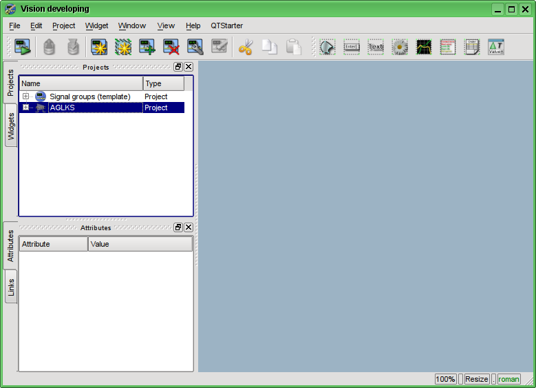
Fig. 3.3. Window of the UI development.
Then we can start the "AGLKS" project's execution. To do this, select it in the list of projects and run by clicking on the first left icon on the toolbar or in the the popup menu. The result will be the window of user interface (Fig.3.4).
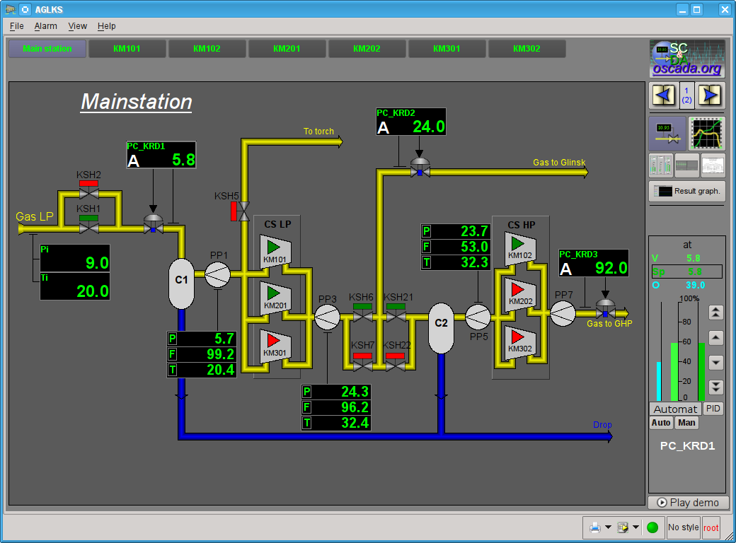
Fig. 3.4. Window of the user interface of the "AGLKS" project.
Building and executing of the user interfaces is implemented by the Vision module of the "User interfaces" subsystem. In addition to this module it can be accessed the other modules of visualization. For example, OpenSCADA provides the WebVision module, which allows to execute projects, previously developed in the "Vision" interface module, through the Web-based technologies and standard Web-browser. All actions in the future we will make only in the interface of the "Vision" module.
So we ran the demonstration of OpenSCADA and familiarized with the main set of tools. In the future we will use them for configuration of OpenSCADA, creating the tasks of data acquisition, binding the collected data with the purpose of their processing and making the impacts, as well as to create the visualization user interface of the received data and to make the control actions.
Lets close the window of the "AGLKS" project's execution and the window of the user interface development to prepare for the study of the following chapters.
The whole process of SCADA-system's configuration to perform the "top level" functions can be divided into two stages:
- The configuration of data sources and creation the database (DB) of the parameters from these sources.
- Formation of a visual presentation of technological process (TP) data by creating the operator's interface in the form of: mnemonic schemes, groups of graphs (trends), groups of contours, documents, etc.
3.1.Creation the user's project from scratch
All the actions in the following sections are described in the "AGLKS" (demonstration) model database environment with the purpose of the widest and the most descriptive presentation of the configuration process, with the ability to connect to a real-live data source, realized on the basis of the gas compressor station TP model. However, it is necessary to describe the process of creation a user project from scratch, which is obviously your final goal. On the basis of a new user's project you can perform all the following steps with the "AGLKS" model database, but with an eye to your own data sources of a new project.To start a clean user's project there is the item "OpenSCADA System" with the characteristic icon in the desktop environment menu, the "Graphics" section (Fig.3.1.1).
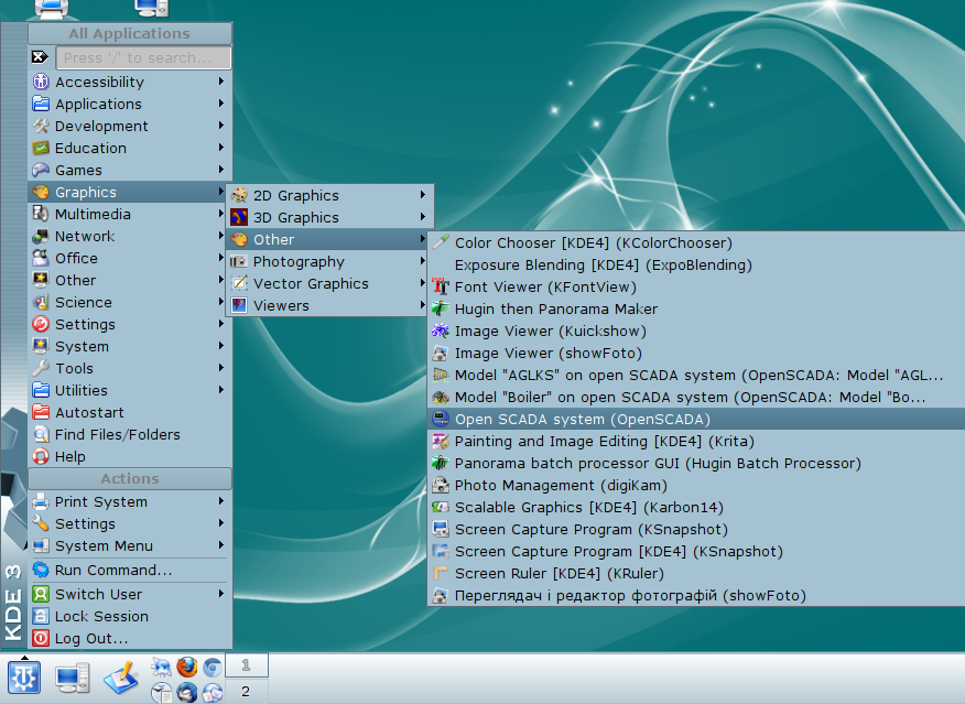
Fig. 3.1.1. Menu item of the desktop environment to start the clean user's project.
The start can also be done with the following command:
Starting from version 0.9 of OpenSCADA the command call cause creation the dialog for new project creation or using pre-installed and user's projects. For selection and new project name dialogs building supported the dialog programs, into the priority checking: dialog (for active terminal present), kdialog (Fig.3.1.2), "zenity" and "Xdialog". Let select the menu item "<New project>" and enter the project name "start" into next dialog.
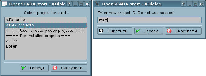
Fig. 3.1.2. The dialog of selection new project creation or using pre-installed and user's projects.
A clean user's project does not contain any project-specific configuration and is configured to work in the user's directory "/.openscada", with the main SQLite database in the file "DATA/MainSt.db". It is easier to create a complex SCADA-system's project using the libraries of API functions of the OpenSCADA object model, libraries of graphic elements, as well as with the help of other OpenSCADA libraries. To use the OpenSCADA libraries, stored in a database file, they need to be connected, added in the "SQLite" database module's object (Fig.3.1.3), as well as it is necessary to set the address and the database charset to "UTF-8" (Fig.3.1.4).
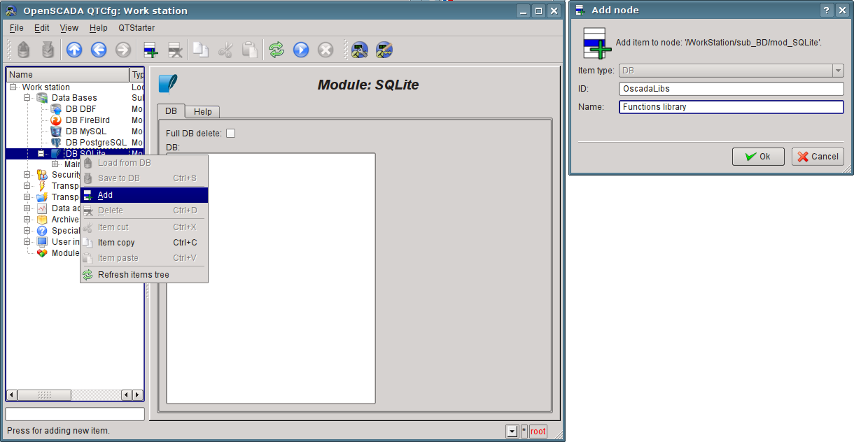
Fig. 3.1.3. Add the "SQLite" DB object.
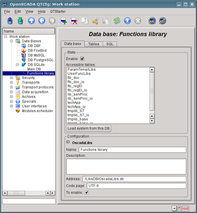
Fig. 3.1.4. "SQLite" DB object of OpenSCADA library.
OpenSCADA distributions supplied with a number of libraries in the form of "SQLite" database files (Table 3.1), which, when you run the clean user's project are placed to the "LibsDB/" directory. According to this list, lets add them in the "SQLite" database module's object, set the "Enabled" flag and save. Next, to load the library contents it is necessary to enable the database and click "Download this system from the database", but during the loading some of new objects are disabled so it's easier to complete a exit user's project and start over again.
Table 3.1. OpenSCADA libraries included in the distribution.
| ID | Name | Address | Languages/charset |
| OscadaLibs | Functions libraries | ./LibsDB/OscadaLibs.db | EN,RU,UK/UTF-8 |
| vcaBase | VCA: Main libraries | ./LibsDB/vcaBase.db | EN,RU,UK/UTF-8 |
| vcaTest | VCA: Tests | ./LibsDB/vcaTest.db | EN,RU,UK/UTF-8 |
| vcaElectroEls | VCA: Electrical elements library of the user interface | ./LibsDB/vcaElectroEls.db | EN,RU,UK/UTF-8 |
After the addition of OpenSCADA libraries you'll get an environment ready for addition of data sources and the formation of the new SCADA-system project's interface.
4. Working with Data Sources
The main function of any SCADA-system is to work with data sources of realtime, namely the inquiry of programmable logic controllers (PLC) and simple modules of CPI. For more details see the document "Data acquisition in OpenSCADA" on the following link: http://wiki.oscada.org/HomePageEn/Doc/DAQ.Support of the one or another data source depends on the protocol or API, through which the source provides its data, and the availability for the protocol/API the module in the subsystem "Data acquisition" in OpenSCADA. The total list of modules of the subsystem "Data acquisition" and documentation on them can be found here http://wiki.oscada.org/HomePageEn/Doc#h735-4 in the appropriate chapter.
Obtained from sources data subsequently are archived, processed and used for visual representation for the operator of TP.
4.1. Data acquisition from the TP device
As an example lets examine and create the inquiry for the air cooler device. Demo database contains the real-time model of the compressor station with six compressors. Data for two devices of air coolers "AT101_1" and "AT101_2" of the compressor station "KM101" are available via the ModBus/TCP protocol on the 10502 port.We will create the inquiry controller's object via the ModBUS/TCP protocol and get these data, thereby practically made the task of inquiry of real data, because from the external device our configuration will be different only in address of the device, addresses of the ModBUS registers and maybe the interaction interface.
There is "ModBUS" module in the "Data acquisition" subsystem for the data acquisition via "ModBUS" protocol in OpenSCADA. To add a new controller we will open the page of the "ModBUS" module in the configurator ("Demo Station"->"Data acquisition"->"Module"->"ModBUS") and in the pop-up menu of the "ModBUS" item lets click "Add" (Fig. 4.1.1).
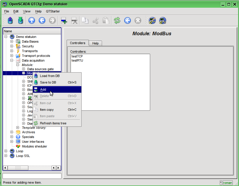
Fig. 4.1.1. Adding the controller in the "ModBUS" module of the "Data acquisition" subsystem.
At the result of our actions the dialog window will appear (Fig.4.1.2) to enter the ID and name of the new controller. IDs of any objects in OpenSCADA are limited by 20 characters and they should be entered using English alphabet characters and numerals. In addition, it is desirable to start the ID with the letter. This is due to the fact that the identifier can later be used in scripts. The OpenSCADA objects' names are limited by 50 characters and can contain any characters. The names are usually displayed. If the name field is blank, instead it the identifier will be displayed. Enter the ID "KM101" and the name "KM 101".
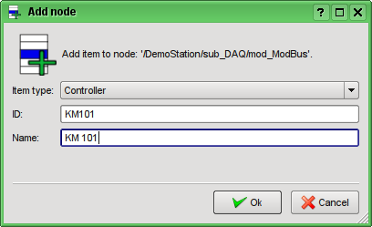
Fig. 4.1.2. Dialog to specify the ID and name of the new object.
After confirmation we have a new controller's object. Lets choose it in the configurator and get acquainted with its settings (Fig.4.1.3).
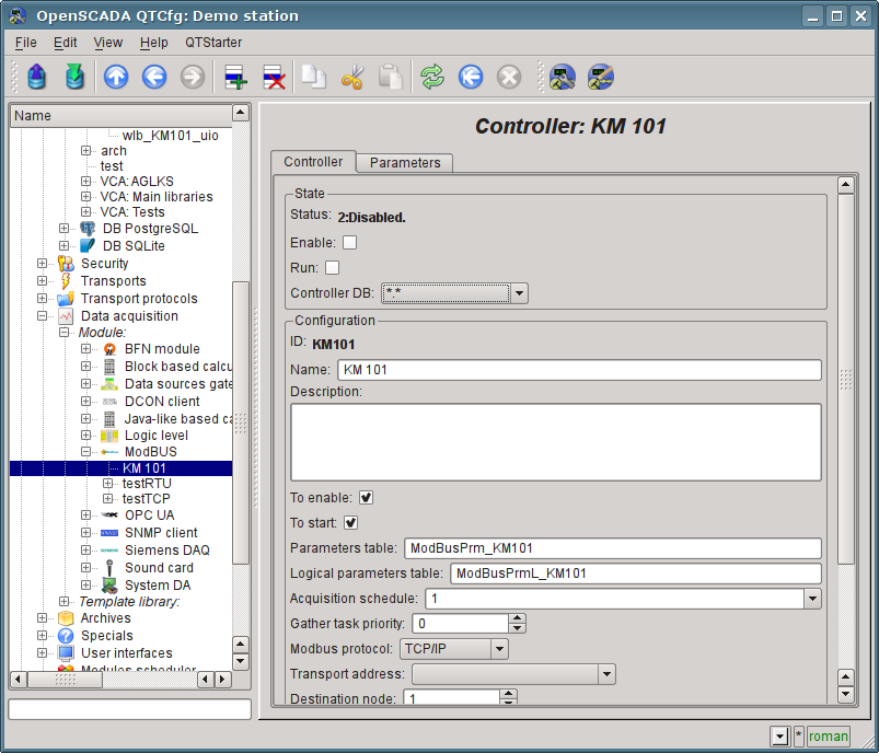
Fig. 4.1.3. The main tab of the controller's object settings of the ModBUS module.
Settings of the controller's object, as a rule, are specific for the different types of data sources and protocols. You can familiarize in details with the settings of the controller's object of the ModBUS module using the link http://wiki.oscada.org/HomePageEn/Doc/ModBus#h871-13. We'll examine the general configuration of the controller's object and the key settings for the ModBUS module.
Before the connection configuration with your controller you need from the controller's documentation to find the settings of network interfaces and protocols, and also, in the case of "ModBus" using, to get the association table for external and internal controller's signals with the numbers of "ModBus" registers.
With the help of the page of the controller's object in the section "Status" may be primarily assessed the current state of the controller's object and the real state of connection with the physical controller, as well as it can be quickly changed. For example, field "Status" contains the code of error and the textual description of the current state of connection with the controller, in this case the controller's object is disabled. We are able to enable it and start by setting the flags beside the appropriate fields. Enabled controller's object initializes the parameters objects, the running one runs the acquisition task and provides an opportunity to transmit data to the controller through the attributes of the parameters. The DB field indicates which database to store in the configuration of the object. We will store the data to main database, ie leave it by defaults.
In the "Config" section the configuration of the controller's object is directly contained:
- "ID" and "Name" are the fields, we've just entered at the object's creation. The Name can be changed right here, but the ID can not be changed so simply. If you want to change the ID you must Cut (Ctrl+X) and Paste (Ctrl+V) the object and enter the desired ID.
- "Description" may contain the detailed description and purpose of the controller's object. In our case, the value of this field is not principal.
- "Enable" and "Run" indicated the state, in which to transfer the controller's object at start of OpenSCADA. Lets set both fields.
- "Parameters table" contains the name of the database's table in which to store the configuration of parameters of the controller. Leave it default.
- "Acquisition schedule" contains the configuration of the scheduler to run the inquiry task. To get the description of the format of the configuration of the field you can from the tooltip. The single number indicates the periodicity of run in seconds. Let it be one second.
- "Gather task priority" indicate the priority of the task (from -1 to 99). Priorities above zero are meaningful only when you start OpenSCADA from the privileged user. Leave this field unchanged.
- "ModBUS protocol" indicates to variant of the ModBUS protocol. The protocol variants possible "TCP/IP", "RTU" and "ASCII". At the moment we are interested in the option "TCP/IP", so leave it as is. The protocol variants "RTU" and "ASCII" need for set at case communication with the controller by serial interfaces, typically "RS-485".
- "Transport address" indicates the outgoing transport of the subsystem "Transports", which is used to connect to the controller. In the case of "TCP/IP" option we need the transport module Sockets, and in case variants "RTU", "ASCII" and serial interfaces we need the transport module Serial. We'll examine the creating of the outgoing transport in "Sockets" and "Serial" in details below.
- "Destination node" indicates the node of data source or conroller in ModBUS network. In our case, it should be "1".
- "Data fragments merge" includes the merging not related fragments of registers in the single block of the request, up to 100 registers, instead generating individual requests. Allows you to reduce the total time of the inquiry. Lets set this option.
- "Using write functions for more items (0x0F,0x10)" instead one-item write will used multi-items functions. Leave this field unchanged.
- "Connection timeout" indicates how long to wait for the response from the controller and after which to report an error of connection. Zero indicates the use of time of transport. Unchanged.
- "Restore timeout" specifies the time in seconds after which if there is no connection to retry to reconnect.
- "Maximum request block size (bytes)" maximum size (bytes) of registers and coils blocks set. Usefull for some controllers with like limits. Unchanged.
Lets save our changes to the database by clicking the second left icon on the toolbar.
Now, in the same manner as the controller's object, let's create the outgoing transport in the module "Sockets" ("Demo Station" ->"Transports"->"Sockets") through the context menu (Fig.4.1.4). And let's call the transport as well as the controller: "KM101" and the name "KM 101". Note that in the "Item type" of the dialog (fig.4.1.2) you should choose the "Output transport.
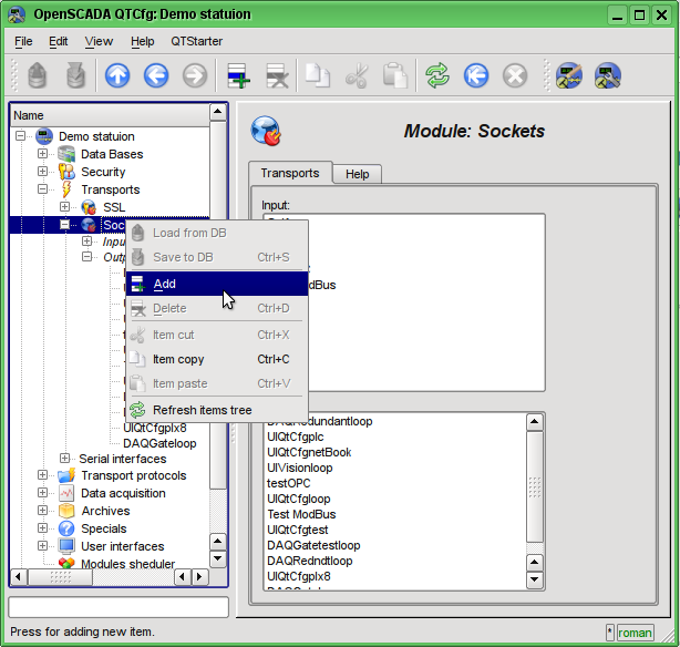
Fig. 4.1.4. Adding the outgoing transport in the module "Sockets" of subsystem "Transports".
The configuration page of outgoing transport is shown in Fig.4.1.5. This page also contains the section of the status and operational control. In the "Status" field the textual description of the current state of transport is contained. We can run it for execution by checking the box in front of the appropriate field. Running object of the transport initiates the connection to the external node. Field DB indicates the database to store the configuration of the object. We will store it in the main database.
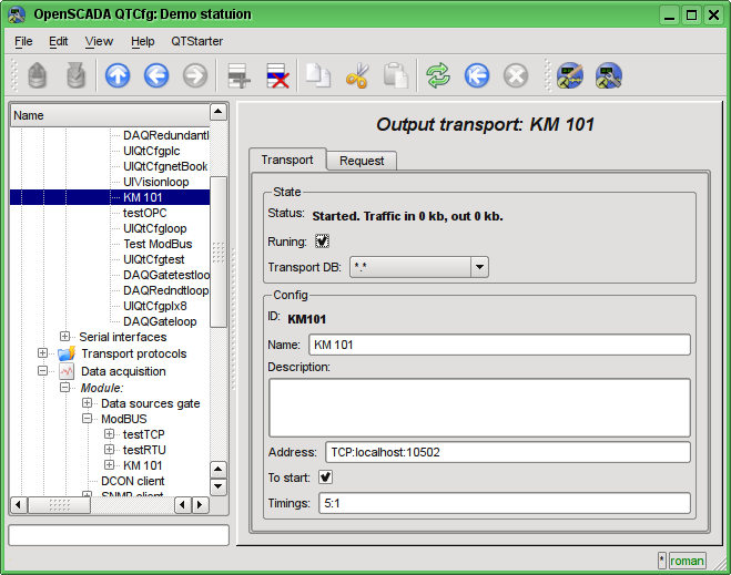
Fig. 4.1.5. The configuration page of the outgoing transport of the "Sockets" module of subsystem "Transports".
In the "Config" section the configuration of the transport object is contained:
- "ID" and "Name" contain the titles, which we entered when creating the object.
- "Description" may contain the detailed description and purpose of the object.
- "Address" specifies the type, address and mode of connection with the remote station. You can view the record format in the tooltip. Let's set this field to the value "TCP:localhost:10502".
- "To start" indicates in what state to transfer an object at start of OpenSCADA. Let's set the field.
- "Timings" indicate the duration of waiting for the response from the remote station. You can view the record format in the tooltip. Let us leave the value unchanged.
Other types transports created by like to "Sockets" method, but configuration typical different only at record format for address and timings. In case of transport module "Serial" into address field write the path to serial device, speed, and format. For converters USB->Serial that address you need learn into operation system, for example by console command "$ dmesg", just after the converter connection.
Let's save the transport and return to the configuration field "Transport address" of the controller's object and select the address "Sockets.KM101". Setting the controller's object is finished, enable it by set flag "Enabled". The next step is configuration and choose the data you need to query from the controller. This setting is done by creating an object "Parameter" of the controller. The "Parameter" object allows you to describe the list of data obtained from the comptroller and to transmit them to the environment of OpenSCADA.
To add a new object of the parameter we will open in the configurator the page of our controller's object and on the popup menu of item "KM101" we'll click "Add". The parameter's object we'll call "AT101_1" and the name "AT 101_1".
The configuration page of the obtained parameter is shown in the Fig.4.1.6. This page contains the section of status and operational control. In the "Type" field it is contained the ID of the type of the parameter, in this case it is only possible the "Standard" type (std). We can enable the parameter by checking the box of the appropriate field. The enabled parameter is involved in the process of exchange with the controller.
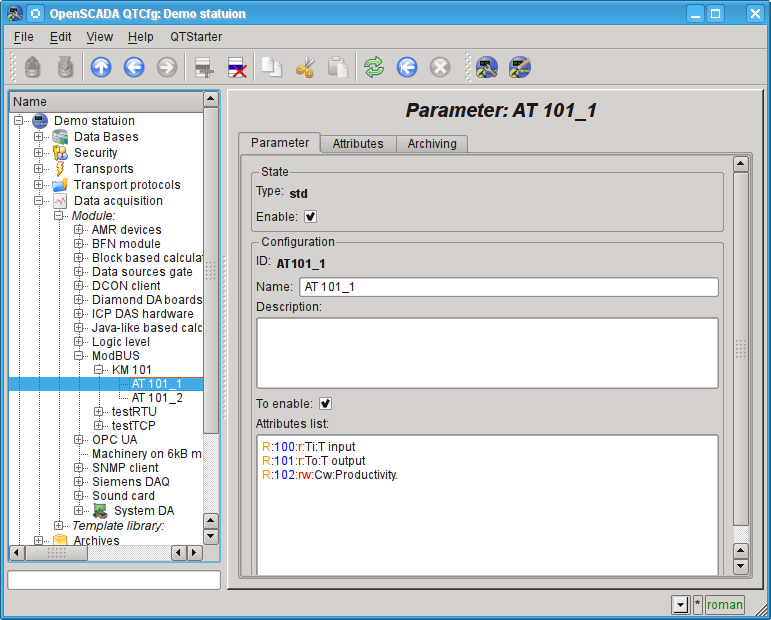
Fig. 4.1.6. Configuration page of the controller's parameter "ModBUS".
In the "Config" section the configuration of tge parameter's object is contained:
- "ID" and "Name" contain the titles, which we entered when creating the object.
- "Description" may contain the detailed description and purpose of the object.
- "To enable" indicates in what state to transfer an object at start of OpenSCADA. Let's set the field.
- "Attributes list" contains the configuration of attributes of parameters in relation of them to the registers and bits of ModBUS. You can view the record format in the tooltip. Let's set the contents of the text field as follows:
Similarly, create the second option: "AT101_2" with the name "AT 101_2". The list of attributes fro it let's set in:
Let's save the both objects of the parameter. Now we can enable and run our controller to initiate the exchange. To do this, go back to the page of our controller's object and in the "Status" section let's set the flag "Run". If we do not miss something, the exchange is successfully started and in the "Status" field we'll get something like this, as it is shown in the Fig.4.1.7.
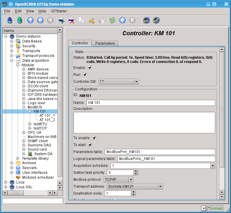
Fig. 4.1.7. The page of the controller's object if the exchange with the physical controller is successful.
In the case of a successful exchange with the physical controller, we'll obtain the described data of the controller in the infrastructure of OpenSCADA. You can see these data on the tab "Attributes" of our parameters AT101_1 (Fig.4.1.8) and AT101_2. Because the inquiry is regularly and at intervals of a second, then we can observe their changes by clicking the button "Refresh current page" on the toolbar.
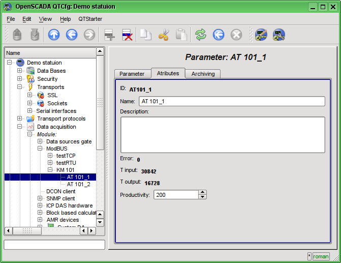
Fig. 4.1.8. The page of described attributes of the AT101_1 parameter.
The configuration of data acquisition is complete.
4.2. TP data processing
Frequently the initial data obtained from the data source are the "raw", ie unprepared or uncomfortable for the visual presentation, so you need to perform this preparation. In our example, we received the data that comes in the code from the scale inside the controller. Our task is to perform the calculation of real values from the received data. Data processing in OpenSCADA can be done, either during the visualization, and in the subsystem "Data acquisition". However, the mixing of the visualization process and processing of initial data makes the configuration confusing and makes the obtained images of the visualization unsuitable for reuse. For this reason, let's make the preparation of data in the subsystem "Data acquisition".Calculations in the subsystem "Data acquisition" are done via the module of logic level LogicLev and the templates of parameters of the subsystem "Data acquisition". To familiarize with the concept of "logical level" you can here: http://wiki.oscada.org/HomePageEn/Doc/DAQ#h942-9.
To make calculations in the module of the logic level you must first create the template of the parameter of subsystem "Data acquisition". To do this, let's open the page of templates' library "Main templates" ("Demo Station"->"Data acquisition"->"Template library"->"Main templates") and through the context menu we will create the template object "airCooler" with the name "Air cooler". The configuration page of the resulting object is shows in the figure 4.2.1. This page contains the "State" section and the section of the operational control. We can make the template accessing by checking the box next to the corresponding field. Accessing templates can be connected to the data acquisition parameters, and the parameters will make calculations on this template. In the "Used" field the number of objects that use this template to calculate the image of the parameter is indicated. In the "Config" section only the familiar for us configuration fields are present.
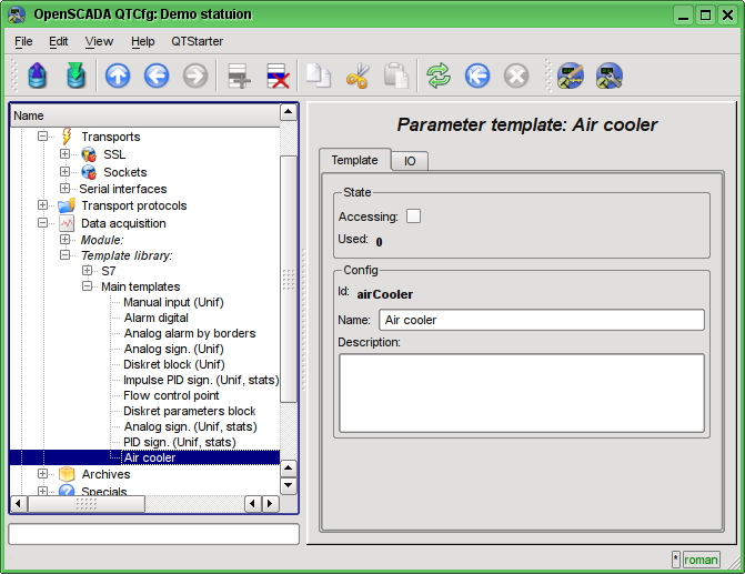
Fig. 4.2.1. The configuration page of the template's object.
The basic configuration and the formation of the template of parameter of data acquisition is made in the tab "IO" (Fig.4.2.2) of the template. The detailed description of the process of the template's formation can be found here: http://wiki.oscada.org/HomePageEn/Doc/ProgrammManual#h932-6.
Let's create in the template two properties fro the inputs ("TiCod", "ToCod"), two for outputs ("Ti","To") and one clear property ("Cw"). For the "TiCod", "ToCod" and "Cw" let's set the "Configure" flag to the "Link", this will let to link to them the "raw" source. For the "Ti" and "To" let's set the "Attribute" flag to the "Read only", and for the "Cw" "Full access", we make it to form the three attributes of the resulting parameter of the data acquisition: two read only and one with the full access.
The program language let's set to "JavaLikeCalc.JavaScript", and the program:
Ti = 150*TiCod/65536;
To = 100*ToCod/65536;
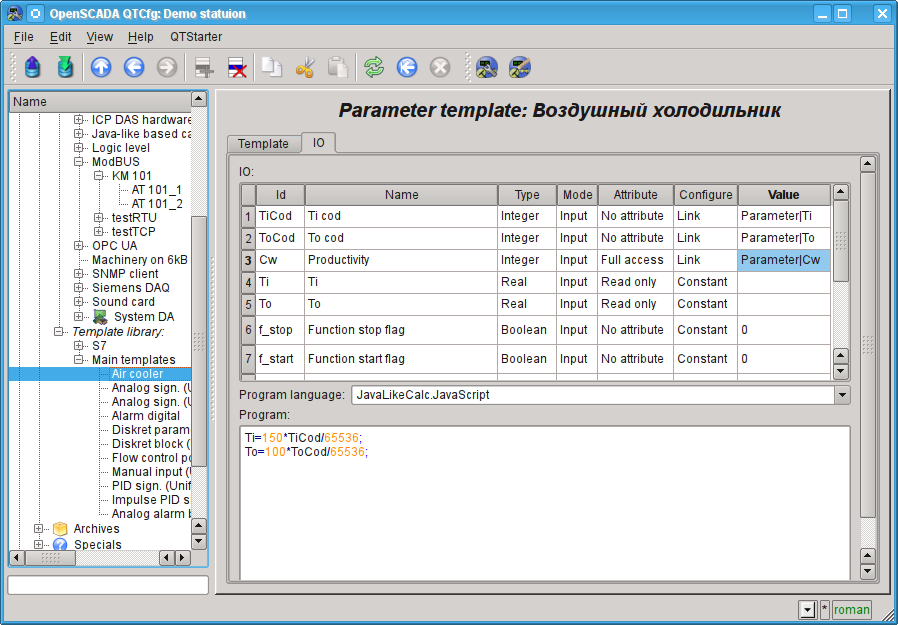
Fig. 4.2.2. Tab "IO" tab of the configuration page of the template's object.
Let's save the resulting template and set the accessibility flag.
Now we'll create the controller's parameters' objects in the "LogicLev" module of subsystem "Data acquisition". The controller and its parameters in the module "LogicLev" are identical to the previously created in the module "ModBUS" and they are created on the page: "Demo station"->"Data acquisition->"Module"->"Logic level". The object of the controller and the parameters will be called identical to the objects in the module "ModBUS".
The object of the controller of the module "LogicLev" (Fig.4.2.3) has no specific settings and the default ones may not be touched.
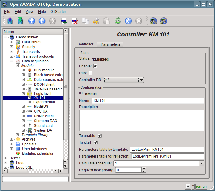
Fig. 4.2.3. The main tab of the configuration of the object of controller of the LogicLev module.
The object of the parameter of controller of the "LogicLev" module (Fig.4.2.4) has the specific setting "Type", where you need to set "Logical" (std) and into setting "Parameter template" select the address of the template, we have just created.
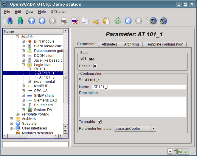
Fig. 4.2.4. Configuration page of the "LogicLev" controller's parameter.
In addition to the basic configuration of the parameter it is necessary to configure the attached template (Fig. 4.2.5). Configuration tab of the template appears in the parameter's mode "Enable". To enable the parameter it is possible by the previously enabling the controller. The flag "Only attributes are to be shown" allows you to set apart each link (Fig.4.2.6). Since we are made the following format of linkage in the template "Parameter|Ti", then all three links we can set simply by typing an address to the parameter in the "ModBus" controller. We shall specify the following addresses "ModBus.KM101.AT101_1" and "ModBus.KM101.AT101_2" in the appropriate parameters.
It should be noted that all the input fields addresses of objects in OpenSCADA provide a mechanism to set the address. This mechanism involves elemental choice, during which there is a movement in the interior. For example, typing the address "ModBus.KM101.AT101_1" first we will be able to choose the type of data source, including the "ModBus". By selecting "ModBus" in the list of available items for selection will be added to the module controllers "ModBus", among which will be "ModBus.KM101". Select the item "ModBus.KM101" add to the list of parameters of the controller, etc. to the final element in accordance with the hierarchy of objects (http://wiki.oscada.org/HomePageEn/Doc/ProgrammManual#h932-6). To be able to return to levels above the selection list of all the elements are inserted into the higher levels of the current value of the address.
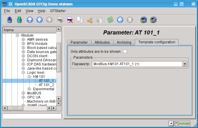
Fig. 4.2.5. The "Template config" tab of the "LogicLev" controller's parameter page.
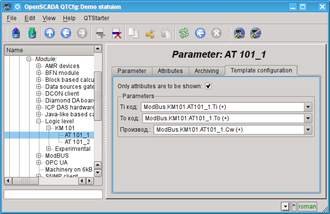
Fig. 4.2.6. The "Template config" tab of the "LogicLev" controller's parameter page with the links details.
Let's save the created objects of the controller and parameters. After this, run the controller for execution by setting the controller's flag "Run" in the "State". If we do not miss something, the calculation is successfully started and in the "State" we'll get something like the one on Fig.4.2.7.
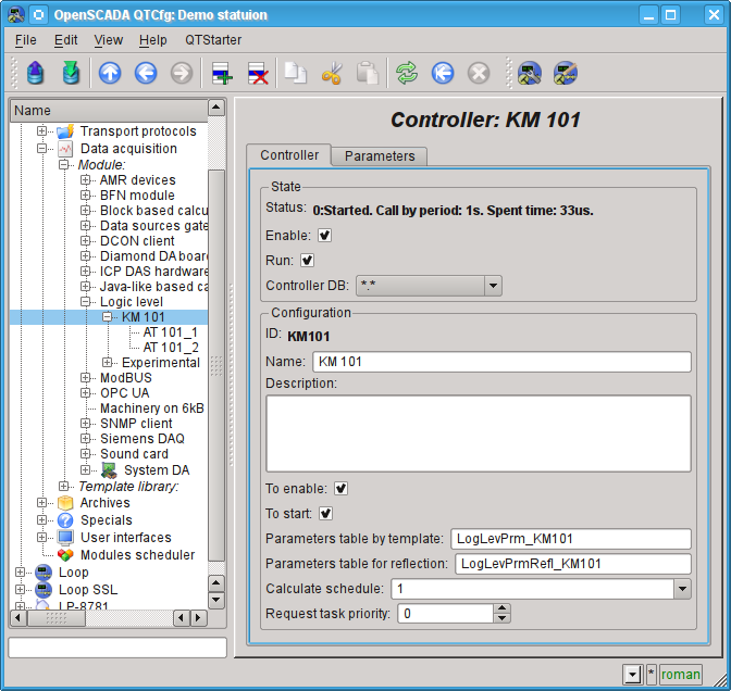
Fig. 4.2.7. The page of the controller's object if the calculation of the controller in the "LogicLev" module is successful.
In case of successful processing of the template's code in the parameters we'll obtain the processed data in the infrastructure of OpenSCADA. You can see these data on the tab "Attributes" of our parameters AT101_1 (Fig.4.2.8) and AT101_2.
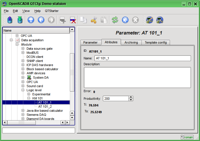
Fig. 4.2.8. The page of the attributes of the parameter AT101_1 of "LogicLev" module.
The configuration of data processing is complete.
4.3. Typified Data Sources Parameters
In the previous sections the data source connection mechanism has been described for the apparatus object ("Air Cooler"), which provides the unification of all signals in a single parameter's object of the data source. However, a more common approach is to create a parameter's object around a signal, such as "Temperature at the cooler's outlet AT101_1 (TE1314_1)".Creating the parameter's object around the signal allows to formalize its description to the templates of analog and digital signals by including to them all necessary processing, alarming and other characteristic information. For a simple configuration of the typified analog and digital signals there are the parameters templates in the OpenSCADA libraries, and many of the visual presentation images are adapted to work and binding with these parameters directly, without going into details on the attributes.
Typically, for the formation of a parameter's object based on a template the logic level module LogicLev is used, as described in the previous section. However, a number of modules, including ModBus provide the ability to immediately create logical parameters, based on the template. We'll add new parameter's objects by opening the early created page of our "ModBus" controller's object in the configurator, and in the context menu of the "KM101" item lets press "Add".
Lets name the analog parameter object "TE1314_1" id and the name is "TE1314_1" (Fig.4.3.1). Parameter's type lets set to "Logical", the parameter's template "base.anUnif", description "The temperature at the outlet of AT101_1", lets set the "To enable" and "Enable" flags. Next, we need to configure the parameter's template in the tab "Template Configuration" tab (Fig.4.3.2): the "Input" field is set to ModBus-register's address of this parameter "R:101", the "Maximum module scale" is set to 65535, which corresponds to 100 °C. Next, lets go to the "Attributes" tab (Fig.4.3.3) and set some fields, "Dimension" is set to "deg. C", "Scale minimum" to "0", "Scale maximum" to "100"; "Border up alarm" to "40", "Border up warning" to "30". Lets save the parameter's object.
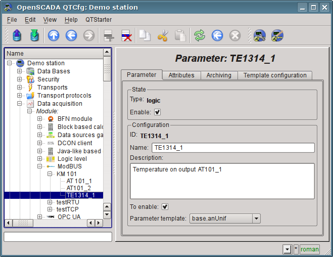
Fig. 4.3.1. The page of the logical parameter "TE1314_1" of the "ModBus" module.
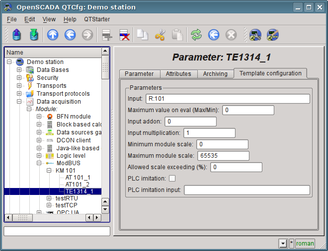
Fig. 4.3.2. The page of the "TE1314_1" parameter's template configuration of the "ModBus" module.
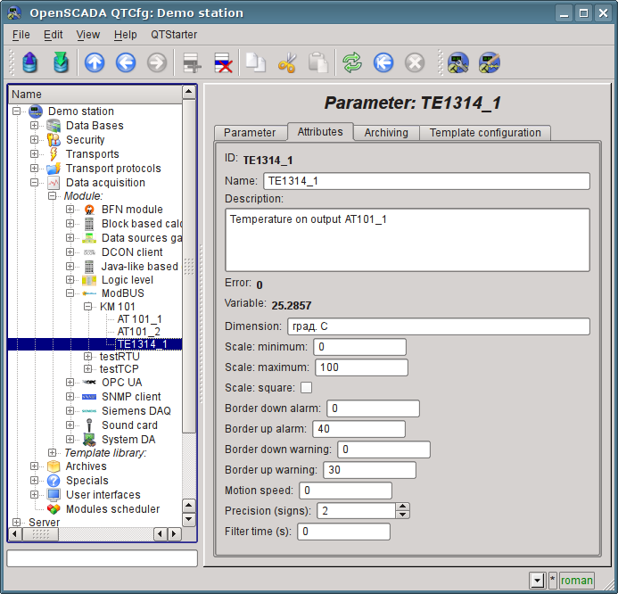
Fig. 4.3.3. The page of the "TE1314_1" parameter's attributes of the "ModBus" module.
The discrete parameter's object lats name: "KSH102" id and the name is "KSH102". Parameter's type lets set to "Logical", the parameter's template "base.digitBlockUnif", lets set the "To enable" and "Enable" flags. Next, we need to configure the parameter's template in the tab "Template Configuration" tab (Fig.4.3.4): the "Command 'Open '" field is set to the value of the ModBus-bit address of the parameter "C:100:rw"; the "State 'Opened'" field is set to the value of the ModBus-bit address "C:101", the "State 'Closed'" field is set to the value of the ModBus-bit address "C:102", the "Hold command time (s)" field is set to 0, because the command if not the pulse one. Next, lets go to the "Attributes" tab (Fig.4.3.5) and make sure the availability of command and states. Save the parameter's object.
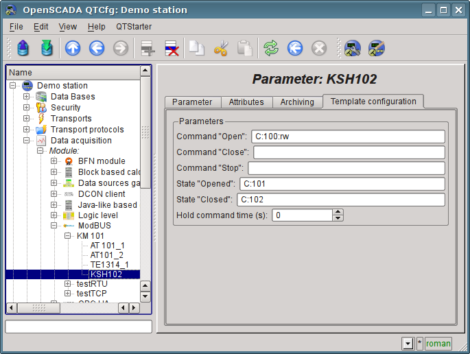
Fig. 4.3.4. The page of the "KSH102" parameter's template configuration of the "ModBus" module.
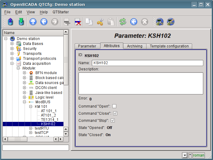
Fig. 4.3.5. The page of the "KSH102" parameter's attributes of the "ModBus" module.
4.4. Enabling the TP data archiving
Many tasks require to keep the history of parameters of the TP. To activate the archiving of the attributes "Ti" and "To" of the AT101_1 and AT101_2 parameters in the previously created controller of the "LogicLev" module it is enough on the "Archiving" tab of the configuration page to choose which attributes are to be archived and by what archivers (Fig.4.4.1). We'll choose the archiving of "Ti" and "To" attributes in the "FSArch.1s" archiver. The same thing you can do for attribute "var" of analog parameter "ModBus.KM101.TE1314_1" and for "com" of digital parameter "ModBus.KM101.KSH102".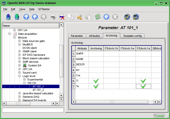
Fig. 4.4.1. The "Archiving" tab of the AT101_1 parameter of the "LogicLev" module.
As the result of this operation it will be automatically created the objects of archives for the selected attributes. For example, the archive's object for the attribute "Ti" of the AT101_1 parameter is presented at Fig.4.4.2.
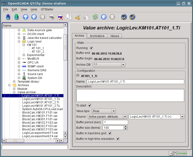
Fig. 4.4.2. The page of the archive's object of the "Ti" attribute of the AT101_1 parameter.
Usually the settings of the archive do not need to be change, but if you need the special configuration, it can be done on the aforesaid page. Often you may need to obtain the information about the archive. For example, find the archive's size, both in time and in the bytes, as well as to look at the graph(diagram) of the parameter (Fig.4.4.3).
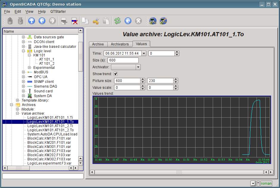
Fig. 4.4.3. The "Values" tab of the page of the archive's object of the "To" attribute of AT101_1 parameter.
5. The formation of visual presentation
The formation of visual presentation may be performed at three levels of complexity and the user can select any of them, depending on the level of his knowledge and availability of libraries with ready-made images and templates.The first level requires a minimum qualification of the user, but implies the presence of template frames' libraries, which are needed to solve his task. Within the limits of the first level the user only has to know how to connect the dynamics to the template frames' pages and how to add new pages of the template frames.
The second level provides the additional ability to create new frames based on the finished complex elements, simply by their placement in the frame. To achieve this qualification level users will need libraries of complex elements needed to solve his tasks.
The third level requires that user is able to use of all the tools of the development environment of visual interfaces of OpenSCADA, including the creation of new complex elements and developing of the new user interfaces in the project.
All works on the visualization interface we will make in an environment of the "Vision" module of subsystem "User interfaces". To open the "Vision" interface window you should click the second icon on the right on the configurator toolbar. The result is the window previously shown in Fig.3.3.
The interfaces of user-operator realizing into OpenSCADA by the projects of visualization. Into library main elements library of the user interface the typical project template has presented, which based on signal objects model and display views concept. The user can start for self concept of visualization interface creation, by new project, or can use pointed template. For new visualization project creation you will need third level knowledges and hard work which placed over this document. By that will see to creation the visualization interface based on allowed template project.
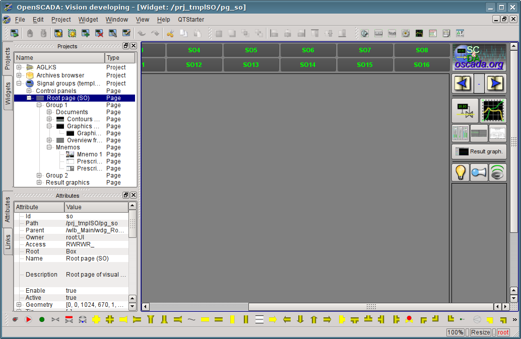
Fig. 5.1. The template project by the signal objects concept.
The template contain two branches: "Control panels" and "Root page". The branch "Control panels" contain typical control panels and special frames set. Branch "Root page", with the root page basis, contain subbranches for signal objects "Group 1", "Group 2" and different branch of "Result graphics". The signal object's subbranches "Group {n}" have number identifier and can expanded by appending up to 16. The subbranch "Group {n}" presenting will display by activation corresponding to it signal object's button on root page, which will allow switch to it. Every subbranch "Group {n}" has containers or templates for display views, typical: "Mnemo", "Graphics groups", "Contours groups", "Groups of overview frames" and "Documents". Any pages present into containers will enable selection the display view, for corresponding signal object of root page. About root page structure you can detailed see by link http://wiki.oscada.org/HomePageEn/Using/GraphicElementsLibraries/MainElements#h1039-45.
For creation self visualization project user can copy the template project and call it for self. We will continue work direct with template project and place our pages into mnemo-containers and graphics groups.
5.1. Adding the template page in the project and linkage of the dynamics
Let's examine the first level of complexity task, when in the already designed interface it is necessary to link the dynamics to the template page. The concept of "Page's template" means the page on the basis of which with the help of inheritance it can be created a lot of final visualization pages with an individual list of the dynamics. The examples of these pages are: "Graphics group", "Contours group", "Overview frames panel" and "Result graphics". In the Fig.5.1.1 the template page "Graphics group" in the project tree "Signal groups (template)" is presented.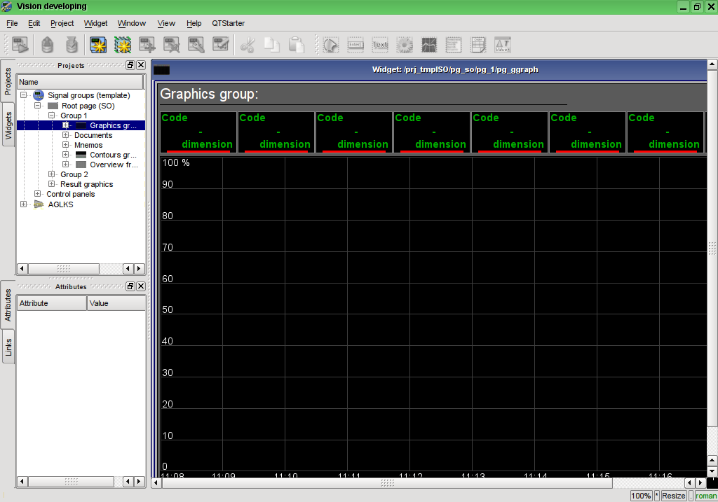
Fig. 5.1.1. The template page "Graphics group".
The "Graphics group" template page provides an opportunity to link up to eight signals for simultaneous display them on the diagram. Elements at the top will automatically hide for unspecified links.
Let's create the new group of graphs "Graphics 2" in the template container "Graphics group" of the first group of the root page of "Signal groups (template)". To do this, let's in the context menu of the "Graphics group" item select "Add visual item" (Fig.5.1.2). To enter the ID and name of the new visual item the dialog will appear (Fig.5.1.3). Enter the ID "2" and the name "Graphics 2".
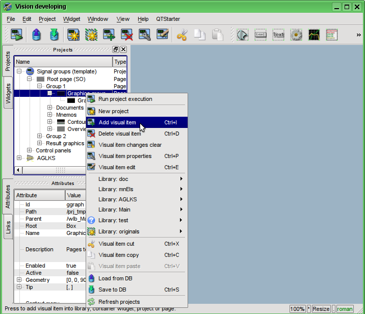
Fig. 5.1.2. Adding the "Graphics 2" group of graphs.
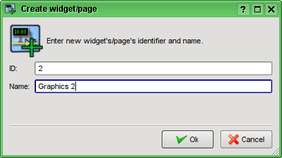
Fig. 5.1.3. Input dialog of the ID and name.
After confirming the name input it will be created the new page. However, for its activation, we need to enable it. You can enable this page in the dialog of the properties editing page (Fig.5.1.4). To open this page it is possible by selecting the menu item 'Visual item properties" in the context menu of the newly created page. New page, based at the template, you can create into the logical container by simple copy template to internal self.
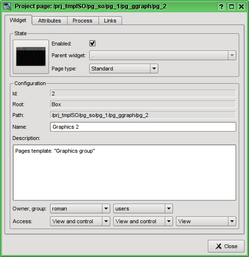
Fig. 5.1.4. Dialogue of the properties editing of the visual element.
After enabling the page you are ready to set links to the created in the previous chapter parameters of controllers. To do this, without leaving the dialog to edit the properties of the newly created page (Fig.5.1.4), click on the "Links" tab (Fig.5.1.5). On this tab, we can see the tree with the elements "el1" ... "el8". Unwinding any of the elements we'll see the "Parameter" branch, in this branch we need to specify or select the address of our attributes "Ti" and "To". Total we will fill the four elements. When filling out the elements the part of properties must be specified as constants. For example, it is necessarily needed to be specified:
- name "val:AT101_1 Ti".
- ed "val:deg.C".
- max "val:150" (for Ti) and "val:100" (for To).
- min "val:0".
If you foresee the existence of the attributes specified in the controller parameter's template as constant, it will be possible to specify only parameter, and the attributes will be set automatically, that you can see to link created early typical analog parameter "ModBus.KM101.TE1314_1".
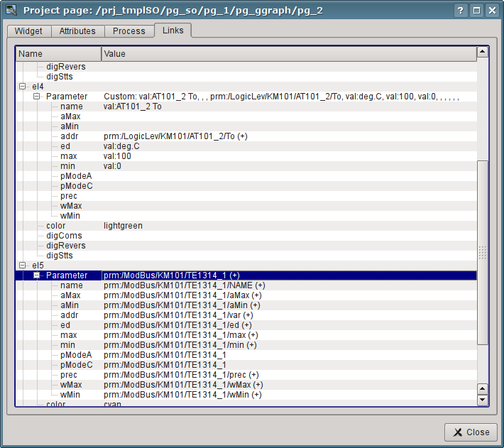
Fig. 5.1.5. The "Links" tab of the dialog of edit the properties of visual item.
Having finished the links entering, we can see the result of our efforts. To do this we'll close the editing properties dialog and run the "Signal groups (template)" for execution, about the run button we remember from the previous chapters. Then let's choose the graphics and switch to the second page. With error-free configuration, we should see something similar to that shown in Fig.5.1.6. Note that for typical parameter, with violations borders set, variable gone to the borders will cause marking by violations color. For see that we can set performance cooler value to 100 (Fig.4.2.8).
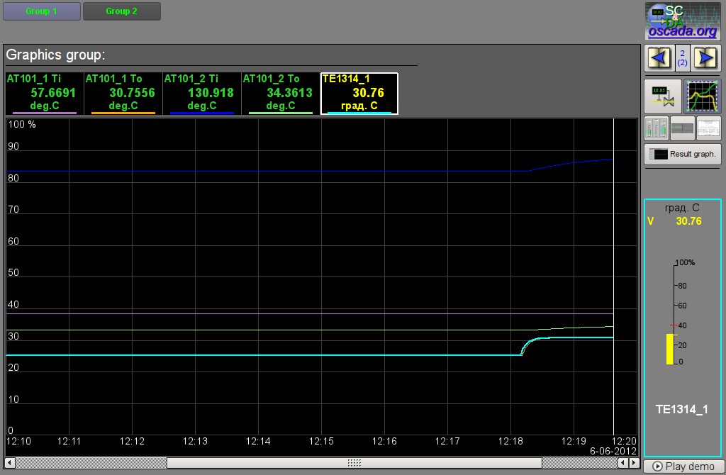
Fig. 5.1.6. The created group of graphs with the four signals and one typical parameter linked.
5.2. The creation of the new frame, the mnemonic scheme
Let's raise the bar and create the new frame, on which we'll put the basic elements of our controllers' values displaying. Such frames are usually called the mnemonic schemes and in addition to the dynamics displaying, and even in the first place, contain the static image of the technological process in the mnemonic representation. We are not going to focus on the creation of statics and we'll add the dynamic elements and link them to the parameters of our controllers. We'll put the created frame to the tree of already known to us project.New frames, destined later to be placed in the project, are to be created in the library of widgets. Let's create the new library of widgets "KM101" by the selecting of the vertical tab "Widgets" and in the context menu of the window of widgets' libraries click "New Library" (Fig.5.2.1). In the dialog of entering the name we'll indicate the identifier "KM101" and the name "KM 101" and then confirm.
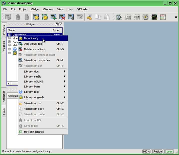
Fig. 5.2.1. Adding the new library of widgets.
Next we'll add the new frame "AT101" by selecting "Library: originals" -> "Elements box" in the context menu of the created library "KM101" (Fig.5.2.2). In the dialog of entering the name we'll indicate the identifier "AT101" and the name "AT 101" and then confirm. At the heart of any frame and the page must be based on an element of "Elements box (Box)", and therefore we have chosen it.
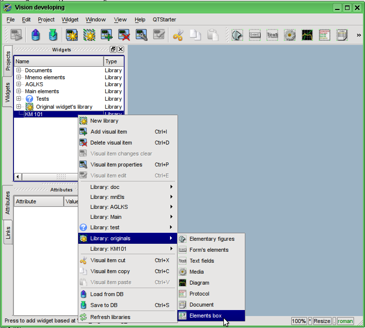
Fig. 5.2.2. Adding the new frame.
Immediately after the creation of the new frame element it is necessary to set its basic properties, characteristic to the mnemonic scheme frame. Properties or attributes of any visual element can be specified in the toolbar "Attributes", having pre-selected the visual element. Let's select the created frame "AT 101" and set the following properties:
- Geometry:width "900".
- Geometry:height "600".
- Page:group "so", for the frame including to mnemo container allow, at run.
- Background:color "#5A5A5A".
- Border:width "1".
- Border:color "black".
The result will be an empty frame (Fig.5.2.3), ready to add items to it. To edit or view the the frame you should in the frame's context menu select the "Visual item edit".
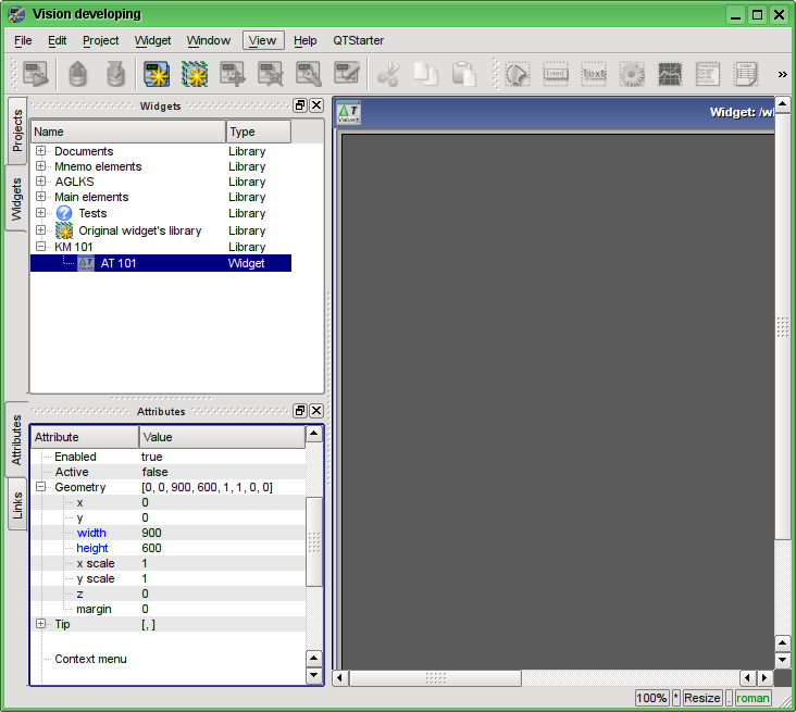
Fig. 5.2.3. The view of the new frame and set attributes for the mnemonic scheme.
Now let's add on frame the elements for the value of the analog parameters displaying for our four signals and typical parameter "ModBus.KM101.TE1314_1". To place an element for displaying an analog signal to the mnemonic scheme it is necessary to select our mnemonic scheme, and then in the window's menu to select the "Widget" -> "Library: Main" -> "Analog show" after which the cursor with an image of this element will appear, which should be moving to the desired location on the mnemonic scheme and then the left mouse button should be pressed. At the time of adding the dialog asking the name of the new element will appear. We'll add this way the five elements which we'll call: "A1_Ti", "A1_To", "A2_Ti", "A2_To" and "TE1314_1".
let's add on the frame the element of typical digital parameter, for that will use library's widget "Widget"->"Library: mnEls"->"Ball crane" and next call it "KSH102".
For list of current violations display let's place on the frame the protocol element from the primitives library "Widget"->"Library: originals"->"Protocol" and next call it "Protocol". For the protocol element will set properties into the attributes inspector:
- Geometry:width "500".
- Geometry:height "250".
- View columns "tm;lev;mess".
- Level "-1", for any level violations display.
- Size, sek "0", for any depth violatons display.
- Tracing period (s) "1".
The added elements can be subsequently positioned as needed by simply selecting and dragging them by the mouse. Also you can change its size. Simple size changing will only resize the container widget geometry, what often needlessly. For all widget's content geometry change it need to scale, what making by key "Ctrl" holding at the widget geometry change or by toggle state "Resize" into statusline to "Scale.
After such manipulations, we should get the mnemonic scheme with the view, similar to Fig.5.2.4.
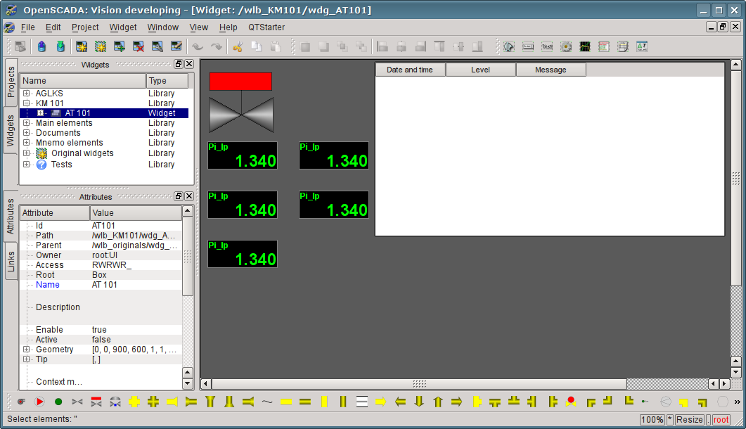
Fig. 5.2.4. The view of the new frame and set attributes for the mnemonic scheme.
This procedure of the creating the mnemonic scheme we'll consider to be finished. Save the new library of widgets "KM101" and proceed to the stage of the placing our mnemonic scheme in the project's tree of "Signal groups (template)".
Let's put our mnemonic scheme to the branch of the "Signal groups (template"->"Root page (SO)"->"Group 1"->"Mnemos" by selecting in the context menu for the "Mnemos" item the item "Library: KM101"->"AT 101". The identifier for the new mnemonic scheme let's set to "2" and the name field let's leave blank.
Next you need to make an already familiar to us the operation from the previous chapter, namely the setting of links to the created in the previous chapter the parameters of controllers. To do this let's open the dialogue of the properties editing of the mnemonic scheme on the "Links" tab (Fig.5.2.5). On this tab, we'll see the tree with the elements of "A1_Ti", "A1_To", "A2_Ti" and "A2_To". Unwinding any of the elements, we'll see the "Parameter" branch, in this branch we are to specify or select the address of our attributes "Ti" and "To", respectively. When filling out the elements the part of the properties must be specified as constants. For example, necessarily must be specified:
- pName "val:AT101_1 Ti".
As in case with graphics group in previous chapter for typical parameters "ModBus.KM101.TE1314_1" and "ModBus.KM101.KSH102" you can set only the parameter and attributes will assign automatic.
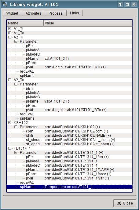
Fig. 5.2.5. The "Links" tab of dialog of editing the properties of the mnemonic scheme.
Now we can save our mnemonic scheme and verify what we have. To do this, we'll close the properties dialog and run the "Signal groups (template)" for execution. Then switch to the second mnemonic scheme by the paging buttons. With error-free configuration, we should see something similar to that shown in Fig.5.2.6.
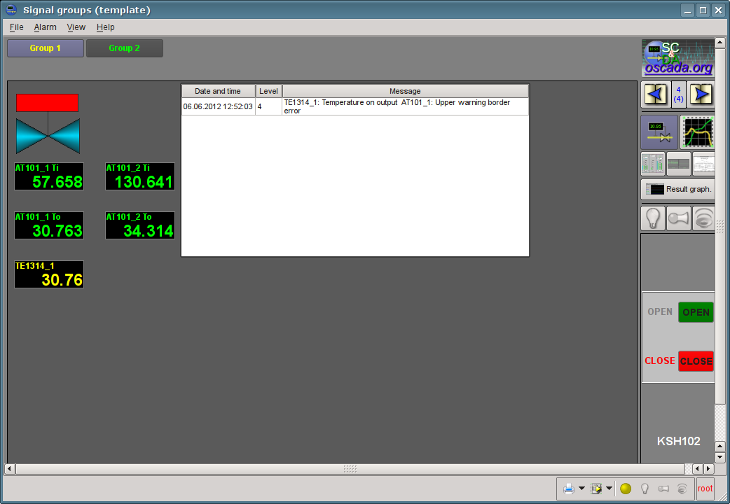
Fig. 5.2.6. The created mnemonic scheme with four linked signals, typical parameters and the protocol.
Note for you, the typical parameter variable going beyond violation borders set will mark by flashing through alarm color: the parameter, the signal object and the yellow circle bottom. On the violation also will cause boozer cheep and speech synthesis (if set and configured program "ru_tts" or other) from the parameter position text into link field "spName" (πθρ. 5.2.5). On the violation will set active the indication buttons on the right and right-bottom, and to press the button will accorded type notification make cvitation. On flashing yellow circle on the right-bottom press will cvitation for all. Any violation allowing fact will noted into the protocol, which we have appended. To see going beyond one violation border we can set the cooler productivity to 100 (Fig.4.2.8). About working with violations concept you can detailed read into chapter "Recipes".
Violations history you can see into document "Protocol of violations", which allowed on the display view "Document" select (Fig.5.2.7).
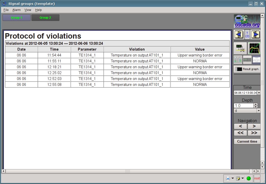
Fig. 5.2.7. Alarms document.
The digital typical parameter "ModBus.KM101.KSH102", displayed by ball crane, is active then you can select it and get control panel on the right (Fig.5.2.6), and also send commands (open or close). The commands you can doing to the control panel or context menu. All operator's control interruptions will noted into protocols and the document for its you can see on the display view "Document" select (Fig.5.2.8).
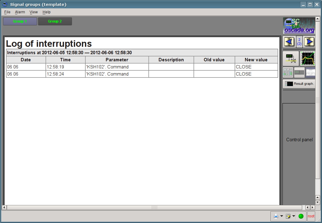
Fig. 5.2.7. The operator interruptions protocol.
5.3. Creation of the new complex element
Let's proceed to the objectives of the third level of complexity, namely the creation of an complex element. Creating of the new complex element, which includes a combination of basic primitives, can be made in several stages. As an example, let's examine the task, consisting of two stages:- Creation the widget "Air cooler" on the basis of the primitive "Elementary figures".
- Creation the final grouped widget "Cooler" based on the primitive "Elements box".
5.3.1. Creation the widget "Air cooler" on the basis of the primitive "Elementary figures".
The widget will be created in our previously made library "KM101". To do this we'll make right mouse button click on this library and select the item "Library: originals"->"Elementary figures", as it is shown in Figure 5.3.1.1. For a new element let's write the "air_cooler" identifier and the name "Air cooler".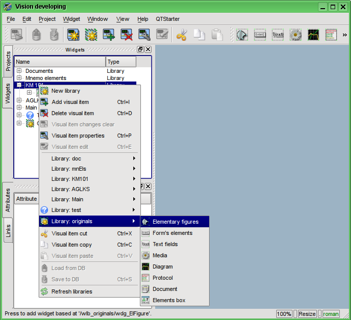
Fig. 5.3.1.1. Adding the widget based on the primitive "Elementary figures" to the "KM101" library.
After confirmation, we will have a new widget's object with the name "Air cooler". Select it in the widget library "KM101" and open for editing via the context menu of the new element (Fig. 5.3.1.2). Let is set properties into attributes inspector:
- Geometry:width "200".
- Geometry:height "200".
- Fill:color "lightgrey". Color may set, as with help
 colors names, and also in format #RRGGBB (#RRGGBB-AAA).
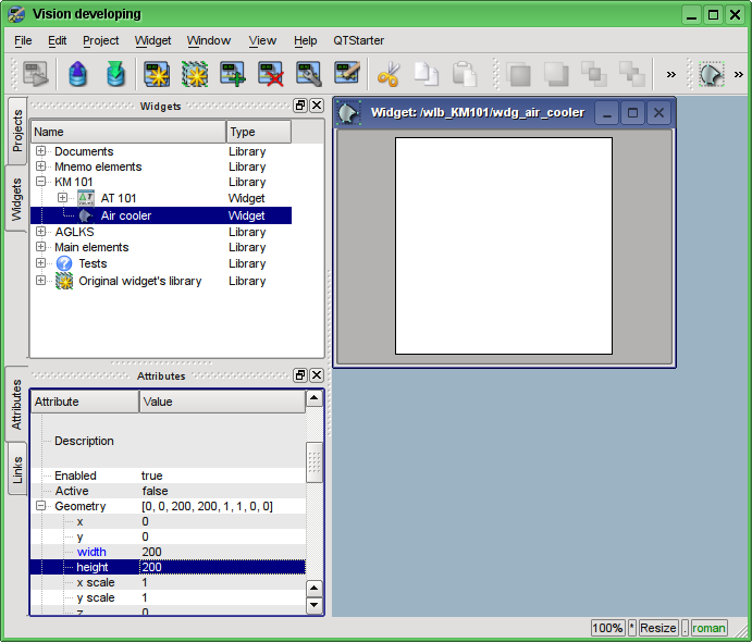
Fig. 5.3.1.2. First widget configuration.
Now let's draw the visual presentation of the widget. This procedure can be done in two ways described below:
- To draw the desired image by the mouse, using the "Line", "Arc", "Bezier curve" and "Fill." The corresponding panel ("Elementary figure tools") appears after entering the edit mode (drawing). To enter this mode it is possible as shown it is shown in Fig. 5.3.1.3, or by double clicking the left mouse button on the body of the widget.
- Manually fill in the "Elements' list", by entering the list of required elements and coordinates of points.
More information about the editor you can get here: http://wiki.oscada.org/HomePageEn/Doc/Vision/ElFigure
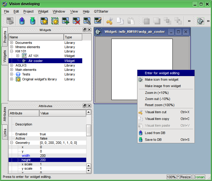
Fig. 5.3.1.3. Entrance to the mode of drawing the widget, based on the primitive "Elementary figures."
In our example, we'll use the second method. To do this in the "Elements' list" of the attributes inspector let's enter the list below and press "Ctrl" + "Enter".
All the points in our case are specified in the static form, since it is not provided the dynamics and change of coordinates in the mode of execution, and all the other parameters are left by default.
As a consequence, our widget will take the form shown in Fig. 5.3.1.4.
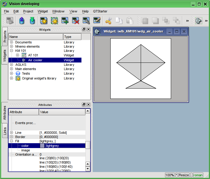
Fig. 5.3.1.4. The image corresponding to the "Elements' list" of the widget.
Let's create an icon for our widget, which will be visible in the widgets' tree of the library "KM101" (Figure 5.3.1.5).
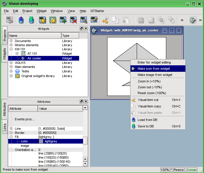
Fig. 5.3.1.5. Creating an icon for the widget.
The process of creating the first widget is completed. We'll now turn to the stage of layout and the creation of the resulting widget.
5.3.2. Creation the final complex widget "Cooler" on the basis of the primitive "Elements box"
The resulting widget we'll create in the "KM 101" library. To do this we must click the right mouse button on the library and select the primitive "Elements box", as it is shown in Figure 5.3.2.1. For a new element let's specify the identifier "elCooler" and the name of "Cooler".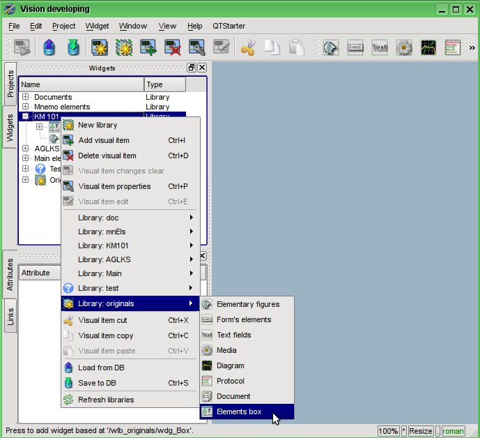
Fig. 5.3.2.1. Adding the widget based on the primitive "Elements box" to the "KM 101" library.
After confirmation, we'll have the new widget object with the name "Cooler". Select it in the widget library "KM 101" and open for editing. Let is set properties into attributes inspector:
- Geometry:width "250".
- Geometry:height "200".
Let's take the previously created element "Air cooler" (air_cooler) and drag him (clicking on it by the left mouse button and moving the cursor of the mouse to the body of the widget, then let the button) to the newly created widget (see Figure 5.3.2.2).
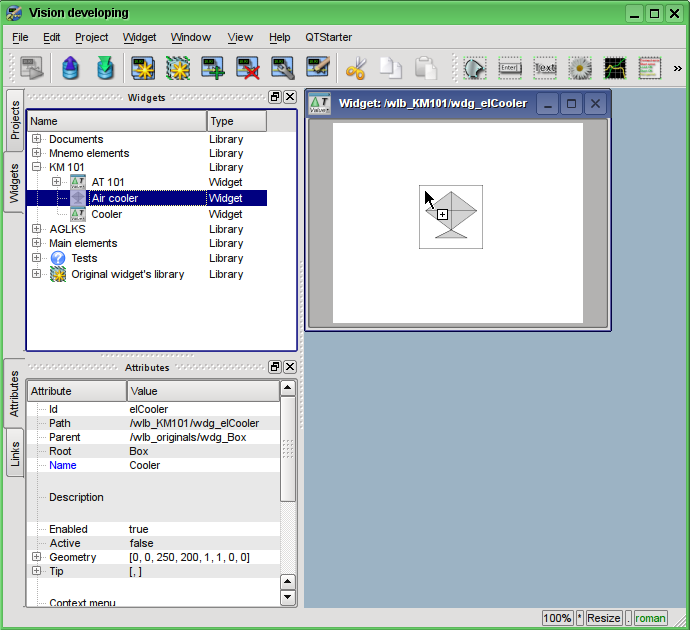
Fig. 5.3.2.2. Drag and Drop of the widget "air_cooler" to the widget-container "elCooler".
The dialogue window will appear to enter the ID and name of the new widget. ID and the name can be set arbitrarily. We will input the "air_cooler" ID and the name we'll leave blank (it will be inherited from parent - the element "air_cooler"). Thus, the newly-created widget inside the container "elCooler" inherits the element - "Air cooler" ("air_cooler"). After confirming the entry of ID and name the widget "Air cooler" ("air_cooler") will be added to our widget container "elCooler" (Figure 5.3.2.3). Let is set properties into attributes inspector:
- Geometry:x "25".
- Geometry:y "0".
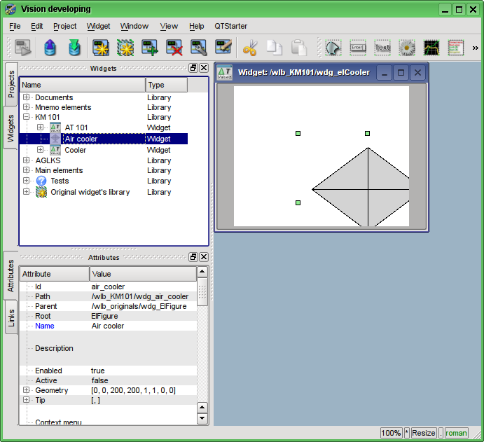
Fig. 5.3.2.3. Adding the inherited widget "air_cooler".
Next, unwind the library "Mnemo elements", find there the "Cooler" element (cooler2) and drag it to the widget-container. This element will dynamically display the productivity of the air cooler. As the result it will appear the dialog window for entering the ID and name of the new widget. Enter the ID "cooler2" and the name again let's leave blank. Thus, the newly-created widget inside the container "elCooler" will inherit the element of the library "Mnemo elements" - "Cooler" ("cooler2"). After confirming the entry of the ID and name the widget "Cooler" ("cooler2") will be added to our widget-container "elCooler". Let is set properties into attributes inspector:
- Geometry:x "75".
- Geometry:y "30".
- Geometry:z "10". Raise the widget over all you can from panel "Widgets view functions".
- Color1 "#FFFF00-200", we have added the value of transparency 200 ("0" - fully transparent, while "255" - the fully opaque), as it is shown in Fig. 5.3.2.4.
- Color2 "#FF0000-200", we have added the value of transparency 200.
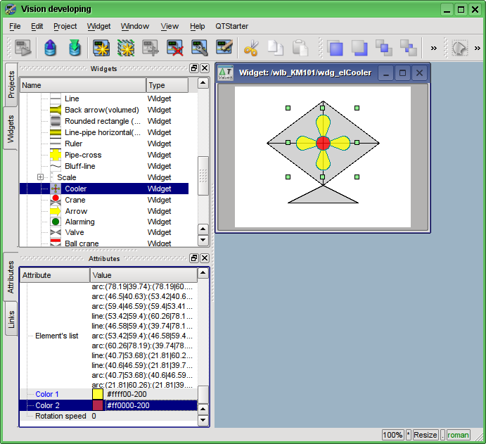
Fig. 5.3.2.4. Change the fill colors transparency in the inherited widget "cooler2".
Now let's add to the widget-container "elCooler" two text fields based on the primitive "Text", in order to display the input and output temperatures of the flow. To do this in the library "KM 101" we'll select the widget "Cooler" and then click on the visual items toolbar on the icon of the primitive "Text", as it is shown in Figure 5.3.2.5. The dialog of the ID and name of the newly created element entering will appear. Enter the ID "Ti" for the first text field, and the name field we'll leave blank. Let is set properties into attributes inspector:
- Geometry:x "5".
- Geometry:y "20".
- ΰ "70".
- ΰ "35".
- Alignment "Center".
- Font "Arial 14 1". Font selection you can do into the dialog which opened at press on the key into edit field (Fig. 5.3.2.7).
- Text "%1{Enter}deg.C" (Fig. 5.3.2.8). {Enter} move to next line.
- Arguments number "1" (Fig. 5.3.2.9):
- Argument 0:type "Real".
- Argument 0:value "300.25", the number "300.25" is entered only the with the purpose of clarity, in the execution mode it will be changed by the real value of the input temperature.
- ΐπγσμενς 0:config "3;f;2".
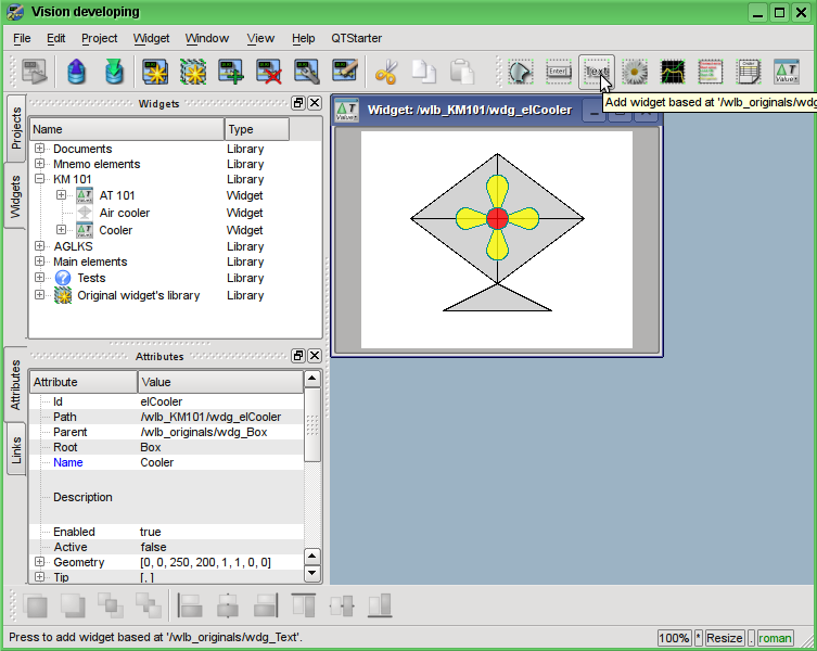
Fig. 5.3.2.5. Adding the new element to the container, based on the primitive "Text."
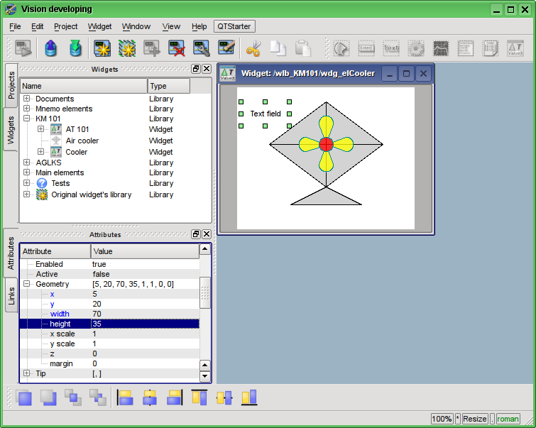
Fig. 5.3.2.6. Specifying the geometry of the widget "Ti".
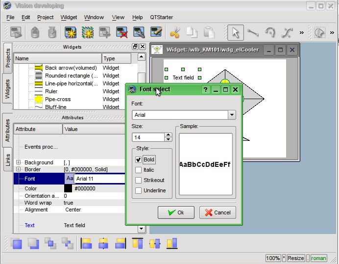
Fig. 5.3.2.7. Changing the font size for the widget "Ti".
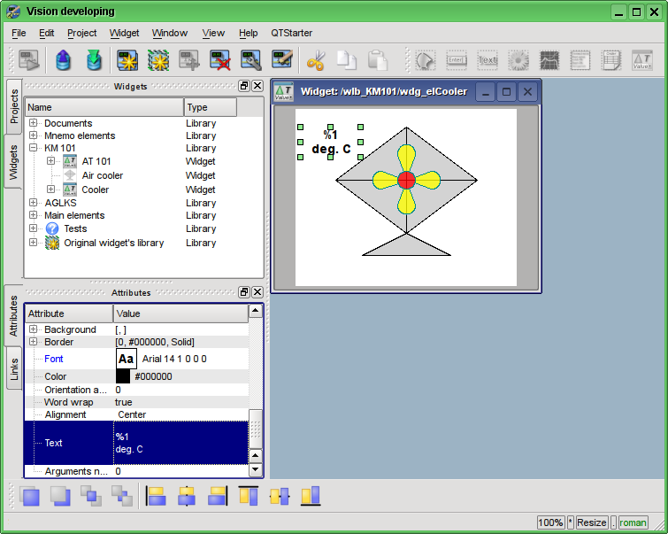
Fig. 5.3.2.8. Changing the field "Text" and an indication of the argument's presence in it for the widget "Ti".
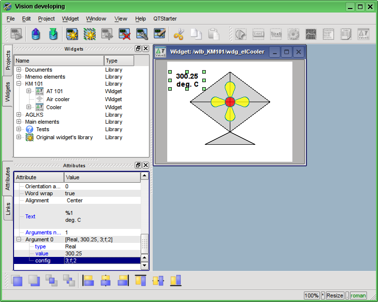
Fig. 5.3.2.9. The configuration of the argument for the "Ti" widget.
Now we'll copy the "Ti" widget in order to create an equivalent widget "To" (output temperature). Let's paste the widget, in the dialog of the ID and the name entering for the newly created widget in the field "ID" we'll write "To", and the name field we'll leave blank (Fig. 5.3.2.10). Let is set properties into attributes inspector:
- Geometry:x "175".
- Geometry:y "20".
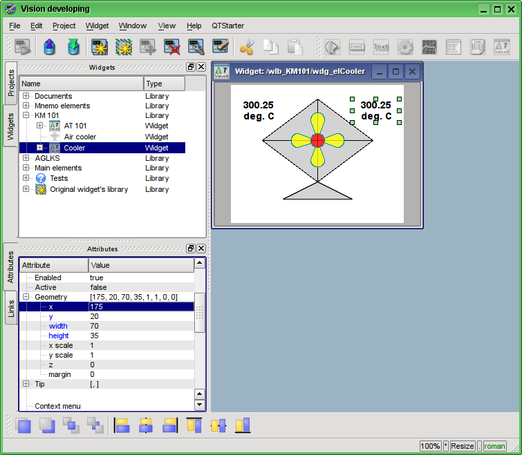
Fig. 5.3.2.10. The "To" widget.
Now let's add the widget based on the primitive "Form's elements" (Fig. 5.3.2.11), which will be used as the ComboBox to select the productivity values of the cooler. The identifier will be "cw", and the "Name" field we'll leave blank (Fig. 5.3.2.12). Let is set properties into attributes inspector:
- Active "true".
- Geometry:x "60".
- Geometry:y "158".
- Geometry:z "10". Raise the widget over all you can from panel "Widgets view functions".
- Geometry:width "60".
- Geometry:height "40".
- Element type "Combo Box".
- Font "Arial 14 1".
- Value "200".
- Configuration "0{Enter}50{Enter}100{Enter}150{Enter}200". {Enter} move to next line.
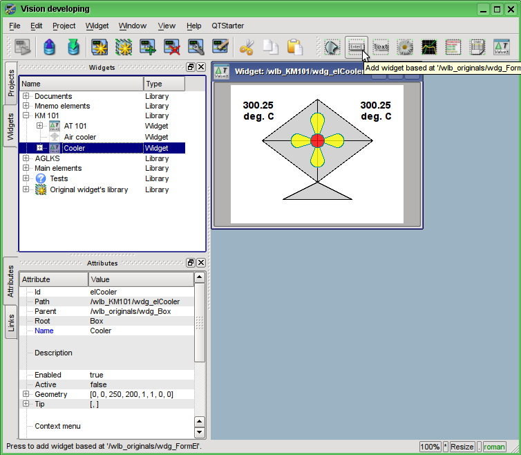
Fig. 5.3.2.11. Adding the widget based on the primitive "Form's elements".
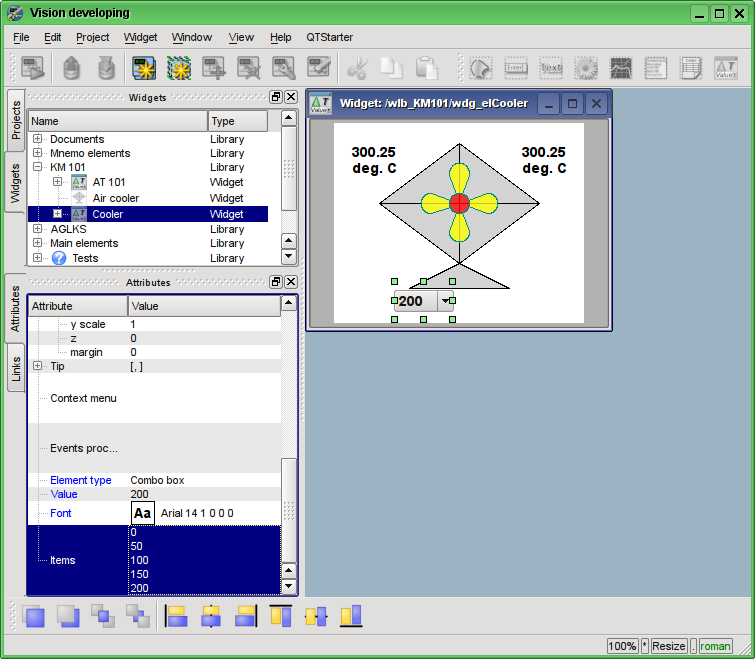
Fig. 5.3.2.12. Filling the parameters of the "cw" ComboBox.
To display the cooler productivity dimensions we'll add the widget on the basis of the "Text" primitive. Let's make the same procedure as for the "Ti" widget. The identifier of the newly created widget will be "dimension" (Fig. 5.3.2.13). Let is set properties into attributes inspector:
- Geometry:x "125".
- Geometry:y "168".
- Geometry:width "60".
- Geometry:height "20".
- Alignment "Center".
- Font "Arial 14 1".
- Text "rpm".
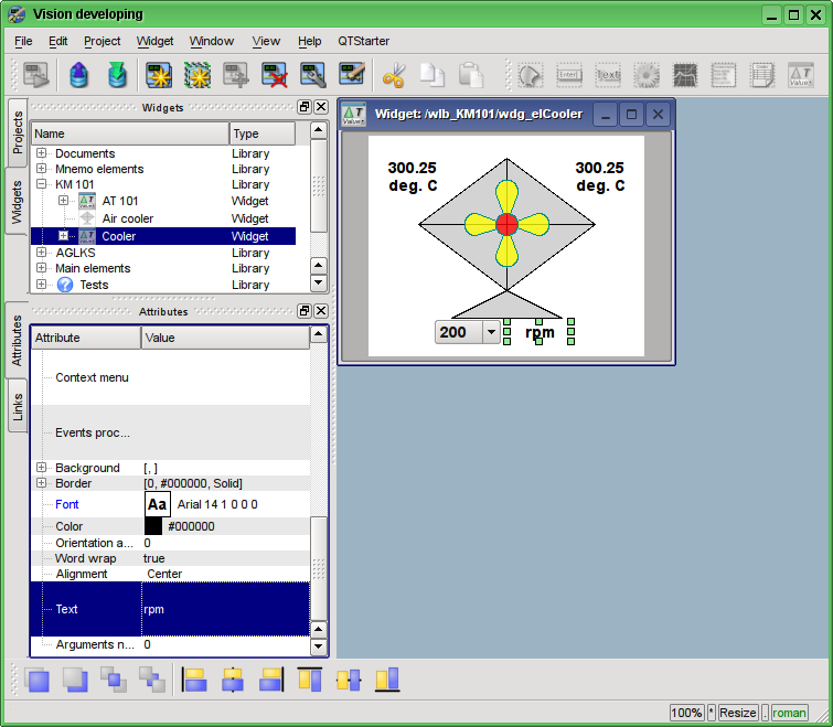
Fig. 5.3.2.13. Adding the "dimension" widget, based on the primitive "Text" and changing of its settings.
To add the processing logics for the widget "Cooler" (elCooler) we'll open the dialog of the properties editing of the visual element and select the "Process" tab. On this tab we can see the tree of widget's attributes and the field for the program code for the attributes' processing. To solve our task, we must add three attributes: Ti, To, Cw (Fig. 5.3.2.14). To add an attribute you should unwind the root element ".", select any element inside the root one and click "Add attribute" button below.
Further we'll enable the processing of "value" attribute of combo box "cw", as it is shown in Fig. 5.3.2.15. Similarly, enable the processing of the "arg0val" attribute for Ti and To, as well as the "speed" attribute of the "cooler2" element.
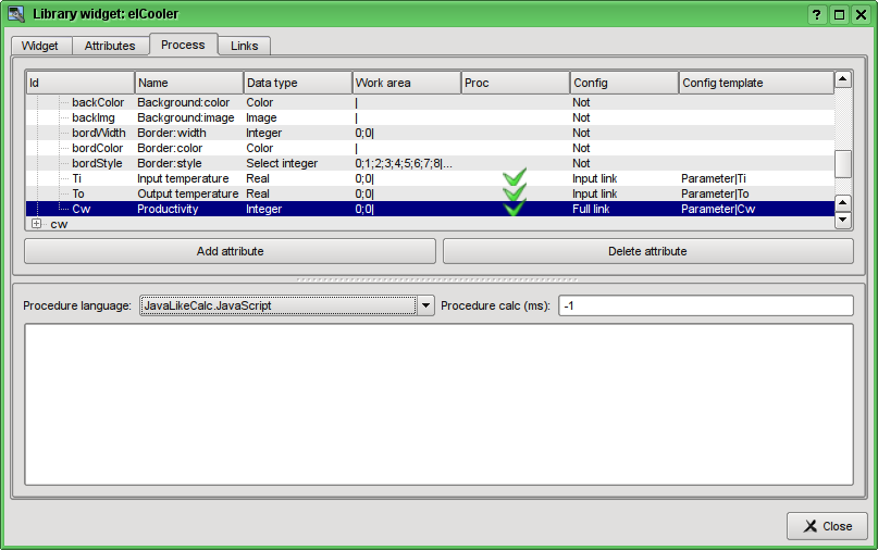
Fig. 5.3.2.14. Adding the three attributes for the element "elCooler" of the library "KM 101".
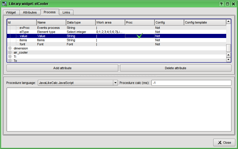
Fig. 5.3.2.15. The enabling of the processing of the "value" attribute of the combo box "cw".
At the end let's set the user programming language for the program to the "JavaLikeCalc.JavaScript" and write the program to process this widget:
Ti_arg0val = Ti;
To_arg0val = To;

ev_wrk = ev_rez = "";
for(off = 0; true; )
{
  ev_wrk = event.parse(0,"\n",off);
  if(!ev_wrk.length) break;
  if(ev_wrk == "ws_CombChange:/cw") Cw = cw_value;
  else ev_rez += ev_wrk+"\n";
}
event = ev_rez;
cw_value = Cw;
cooler2_speed = Cw/5;The resulting view of the Process tab of the "elCooler" widget of the "KM 101" library will have the form shown in Fig. 5.3.2.16.
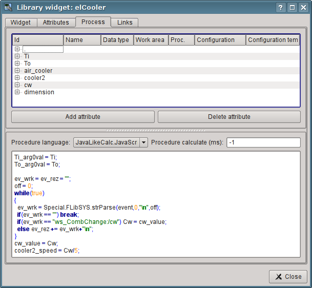
Fig. 5.3.2.16. The resulting view of the Process tab of the "elCooler" widget of the "KM 101" library.
Let's close the dialogue of the properties of visual element editing, create an icon on the basis of our element, close the inner editing window and save it all.
The development of the complex element is finished.
5.3.3. Adding the complex element to the mnemonic scheme
To test the operability and evaluate the results of our efforts let's add the created widget to the mnemonic scheme, developed in chapter 5.2. We'll repeat this operation for two coolers "AT101_1" and "AT101_2".To do this we'll open the frame of mnemonic scheme "AT 101" for editing. Then grab by the "mouse" our complex element and drag to mnemonic scheme, where we drop it in the desired position. In the dialog we'll enter the identifiers "AT101_1" and "AT101_2" respectively. The field "Name" is blank. Added element we'll place the way we desire. After such manipulations, we should get the mnemonic scheme with the view, similar to Fig.5.3.3.1.
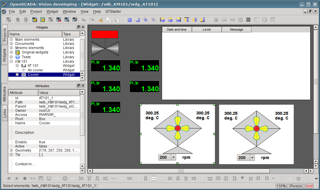
Fig. 5.3.3.1. The view of the mnemonic scheme with complex elements.
Let's save the new mnemonic scheme and close its window. Then move on to the project and open this mnemonic scheme in the project's tree "Signal groups (template)"->"Root page (SO)"->"Group 1"->"Mnemos"->"AT 101". As you can see, our new elements are appeared here automatically. And we only need to connect the links to the new elements. To do this we'll open the dialog of editing the properties of the mnemonic scheme on the "Links" tab (Fig.5.3.3.2). On this tab, we can see the tree with the elements of "AT101_1" and "AT101_2". Unwinding any of the elements, we'll see the "Parameter" branch just with the "Ti", "To" and "Cw" attributes, thus we can simply specify the address of the parameter "prm:/LogicLev/KM101/AT101_1" in the "Parameter" field and attributes will be placed automatically.
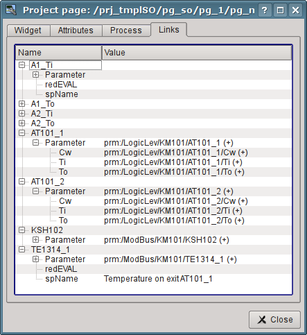
Fig. 5.3.3.2. The "Links" tab of the dialog of editing the properties of the mnemonic scheme.
Let's save our mnemonic scheme and verify what we have. To do this, close the dialog of the properties and run the "Signal groups (template)" for execution. Then switch to the second mnemonic scheme with the help of paging buttons. With error-free configuration, we should see something similar to that shown in Fig.5.3.3.3.
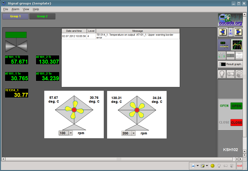
Fig. 5.3.3.3. The resulting mnemonic scheme.
On this mnemonic scheme through our complex elements we can not only observe but also to control the productivity of coolers, simply by changing the value in the combo box. Changing the productivity, we can see the changes in temperature and alarms for analog typed parameter. History of changes we can see on the created in the chapter 5.1 the group of graphs.
6. Recipes (How to)
This section is intended to provide the descriptions of recipes for solving the common problems and tasks of the user. Recipes to be placed in this section may be offered by the users.6.1. Transfer of OpenSCADA configurations from one project to another
It is often needed to transfer configuration from one OpenSCADA project to another. And, more often it is necessary to make a partial transfer, for example, the transfer of certain developments that could be useful in the new project.Generally, it should be noted that any developments with the slightest hint, and the prospect of re-use should be standardized and maintained in the separate, own libraries and databases. It is not recommended to change the default configurations and elements of the standard libraries, and save your own, new libraries and elements in the databases of standard libraries. This will subsequently allow you to painlessly update the standard libraries, and to simply use the developments of your previous projects.
Easy transfer of the DB with libraries and configuration
If you took into account the above recommendations and all of your uniform developments are contained in the separate database, then the entire transfer process will be to copy the database and connect it to a new project.The procedure of DB copying is different for different types of databases and you should read about it in the DB documentation. In the OpenSCADA distros it is commonly used the SQLite database, as separate files *.db. Ρopying of the SQLite database, respectively, is the simple copying of the the required database file from the database directory of the old project to the database directory of the new one.
Connection is made by creating a new database object in the module of the required DB type of the database subsystem and its subsequent configuration (in details). After the creation, configuration, and the enabling of database you can immediately download the configuration from it by clicking the "Load system from this DB" on the form of the database object.
Separation of the desired configuration
If the desired configuration is contained in a common database or in the database of standard libraries, you need to move it to the separate database. You can move the configuration either to a separate database with your libraries or to the export database. Export database, unlike a library one, only serves to transfer the configuration and will subsequently be deleted. In any case, you must create a new database for the desired database type, like the connection procedure above. To transfer you should use a database type that you plan to use in the new project. Usually, it is better to use the SQLite database type for the transfer, because of the simple copying procedure for it. However, if you use a network database, the procedure may change to the simple connection of the library or export database to a new project.Next, you must separate the configuration in unifying or export libraries, if it can not be directly stored in a database. For example, certain templates of parameters or parameters of the data acquisition controllers, visual elements of the widgets libraries etc. You can separate by creating a library of export or by the unification of the element, such as a library of templates, or the controller of the data acquisition parameters, library of widgets etc. For the newly created library as the database should be specified the previously created unifying or export database. Further you should copy the necessary elements from the original library to unifying/export via a standard copy function. After copying the unifying/export library must be saved.
If it is necessary to transfer the configuration element with a separate DB property or the entire libraries the operation of creating an intermediate library and the further copying can be omitted. It is enough in the DB field to specify the previously created a unifying or export database and save the element.
Further actions, namely the simple transfer of the database, are implemented in accordance with the previous section.
When you transfer the configuration by exporting it is necessary to implement the reverse process of copying from the export libraries to the local libraries of a new project and deleting of the export database.
Low-level copy of the DB contents
To transfer you can make selectively copying of the database tables with the configuration by selecting the tables' objects in the database object, the copy command, the selecting of the object of a new database and insert command (in details). However, it is necessary to know the structure of the database, about which you can read by this link.6.2. Cyclic programming into OpenSCADA particularity
Novice users often have question about time intervals hold while programming calculation procedures in the OpenSCADA environment. This question is usually associated with the presence of previous programming experience in linear calculations and lack of experience in programming of cyclic real-time systems.The so-called tact or cycle of periodical calculations, ie the life rhythm is used in the real-time systems. Some procedure is calculated in each cycle that should not take more time than the cycle. As a consequence, if the cycle procedure stops for waiting, the life of the real-time system stops too. Hence, the using of traditional sleep task functions into such procedures is unacceptable!
The solution of the desired exposure time interval in the real-time systems, within the rhythm of life, is made in two ways. The first way is to decrement the counter value, set to the time interval, in each cycle by the cycle frequency to the value <= 0, for example, in OpenSCADA it is implemented as follows:
if((tm_cnt-=1/f_frq) <= 0)  //Decrement
{
    tm_cnt = 10; //Set the counter to a value of 10 seconds
    //Other actions with the periodicity of 10 seconds
}
The second way is based on the astronomical time, ie the comparison with the current time is made in the cycle, for example, in OpenSCADA it is implemented as follows:
if(SYS.time() > tm_to)
{
    tm_to = SYS.time()+10; //Setting the waiting threshold for 10 seconds more than the current time
    //Other actions with the periodicity of 10 seconds
}
The second method is more reliable because it excludes the operation delay problem due to the possibility of calculating the cycle procedure over the cycle time. Although in the properly configured systems and tasks, this problem should not occur.
6.3. Live disk (Live CD/USB)
In order to simplify maximum the OpenSCADA deployment, you can use live builds of boot-able CD and USB disks. Live disk provides the ability to boot directly from it and quickly to obtain the desired working environment. During booting and operating a live disk does not use regular data storages, which means you can not worry about the integrity and safety of data on them. In general, a live disk is a convinient tool with a wide range of necessary software tools, independent from the stationary software environment, and capable to make diagnostics of software and hardware environment, and their restoration in some cases.Live disk is a packaged image of the operating system and applications with a size of about 700MB, recorded on CD/DVD disk or USB-Flash disk. During the operation the operating system "on the fly" unpacks the files needed to run programs and open documents, and therefore does not use memory more than at its usual installation.
The live disks with OpenSCADA built into several variants based on distributive ΞS Linux
- Saving work changes transparently, on writing to USB-Flash. The feature achieved by creation disk's partition to write, on a free USB-Flash space. The partion mirrored to file system's root and all modifications will write to it. Besides the work data saving to the partition you can install needed program packages from the packages repository Debian, OpenSCADA or ALTLinux.
- Combination of typical data storage and live Flash-disk. The feature achieved by writing the live disk's image direct to the USB-Flash file system FAT16 or FAT32, what preserves the typical data storage's functions and appends the live-disk function.
- The live disk environment installation to stationary data storage. That allow for you do not deeply learning to the operation system Linux on it installation, configuration, and also OpenSCADA deployment. You enough to load from the live disk, to check for all hardware correct detection and all need program work, then, by simple procedure aid from the icon on desktop, or the separated boot menu, to install its to the regular storage. The resulting installation will exactly repeat the live disk environment.
Combined-hybrid ISO-image of the live disk
Currently here mostly built hybrid ISO-images of the live disks (*LiveCD_USB.iso), which you can write directly to CD/DVD, USB-Flash, and also extract it content for writing to the USB-Flash with the file system FAT or EXT.The primary variant of the live disk forming is writing to CD/DVD, for what you can use standard tools of the original operating system. But becoming widely it writing to the USB-Flash, what you can do from the environment of Linux, for example, from the environment of this live disc, recorded and booted previously with CD/DVD drive; or from OS MS Windows, by "Win32DiskImager".
Address of the disk for ISO-image recording looks as "/dev/sd{x}", and it can be found by the console command "$ dmesg", immediately after you connect the target USB-Flash drive. From the Linux environment you can write the ISO-image to the USB-Flash like this:
Live USB-Flash disk with file-system FAT or EXT
Earlier performed special buildings of the images to write its on the file system FAT. Currently the special images build only for Firmwares of several PLCs (*flash.tar). But for the live USB-Flash disks of general-purposes creation you can use hybrid ISO-image, about that see to part before.The advantage of the live disk on USB-Flash, as it was previously mentioned, is a combination of USB-Flash drive features as a data storage and as a live disc at the same time. Also on the basis you can create compact, reliable and functional solutions of the embedded systems based on OpenSCADA, such as Programmable Logic Controllers (PLC), the panel controllers (with a touch screen), as well as simple SCADA-servers and operator's "quickly made" SCADA-stations, by recording a live disk to the stationary data storage (HDD, SSD or Flash). The reliability of this solution is achieved by placing the main non-modifiable software in the packed file, and operational data on the journaled file system.
The recording of such image can be done from any operating system (for FAT), but to install the bootloader it is possible only from Linux, for which you can use the CD/DVD disk from the previous section.
The procedure for creating a live disk follow, for the data of the hybrid ISO-disk (Debian and ALTLinux):
- To simplify the operation of extracting and copying of the ISO-data let perform it into the twin-panels file manager mc. For mc allowing to view the ISO-image you need install utility isoinfo, which ordinary places into package "genisoimage".
- Take original file of the ISO-image, open it into mc and copy from it to target FAT or EXT file system:
- Debian: directories "isolinux" and "live"; rename the directory "isolinux" to "syslinux", on the target file system.
- ALTLinux: directory "syslinux" and file "live".
- Rename file "syslinux/isolinux.cfg" to "syslinux/syslinux.cfg", for FAT, or "syslinux/extlinux.cfg", for EXT.
- ALTLinux: Append to the argument "append", of the section "label live" of the file "syslinux/syslinux.cfg", the sub-string "automatic=method:disk,label:MY_LAB" or "automatic=method:disk,uuid:MY-UUID", where MY_LAB and MY-UUID you can obtain, for partition of "the live disk", by the command aid $ blkid.
- ALTLinux: Replace file "syslinux/gfxboot.c32" to analogous file from current file system (ordinary it placed into directory "/usr/lib/syslinux/").
- Install boot-loader from the command line, all from the superuser: $ su -
- Unmount the disk: $ umount /dev/sd{x}1
- Initialize the MBR of the disk to the correct value: $ ms-sys -s /dev/sd{x}
- Initialize the boot loader: $ syslinux /dev/sd{x}1
For creating the live disk image on the FAT (ALTLinux), all operation should be done from root: $ su -
- Connect the target disk and obtain it's address: $ dmesg
- Mount: $ mkdir /mnt/tmp; mount /dev/sd{x}1 /mnt/tmp
- Unpack the contents of an archive on the mounted disk: $ cd /mnt/tmp; tar xvf /var/tmp/LP8x81-ALTLinux6-OpenSCADA_0.9+r2302-i586-plc-rt1-up.flash.tar
- Find out the UUID for the filesystem of the target disk: $ blkid | grep /dev/sd{x}1
- Modify the file "/mnt/tmp/syslinux/syslinux.cfg" at the end of the line "append initrd=alt0/full.cz live ... disk,uuid:4EB3-0478", where it is necessary to set the previously obtained UUID.
- Add or modify the file "/mnt/tmp/syslinux/lang" for specify the locale-language of the interface by default, for the Russian language it is necessary to specify "ru_RU", otherwise it will be English.
- Unmount the disk: $ umount /dev/sd{x}1
- Initialize the MBR of the disk to the correct value: $ ms-sys -s /dev/sd{x}
- Initialize the boot loader: $ syslinux /dev/sd{x}1
Working data of the live disk preserving on a partition of the USB-Flash
The Live disk, as mentioned early, allow you full-featured work with saving the working data, and also updating the programs (excluding the system programs and the OS Linux kernel). Typically that possibility has sense only for USB, HDD, SSD storages.In Debian distribution case a separated partition for the working data storing, with the label "persistence", you need to create especial at anytime, and also into the file "persistence.conf" of the partition you need set the file system or it's part for reflection to writing (for example, "/home"). For reflection to all the file system into the file you need write "/ union". For the partition's file system better use "EXT3", and for it creation you can use a partition management program, for example "gparted".
In ALTLinux (6) distribution case and a hybrid ISO-image direct writing that partition will created at the first start time. During form the live disk on FAT and EXT you need create separated partition with label "alt-live-storage" and the file system "EXT3", that you can do into a partition management program, for example "gparted".
Booting
To boot from the live disk the computer should be rebooted and then you should press the key to enter the BIOS boot menu at the very start of the boot and choose there our disk (Fig.6.3.1). The key to enter the boot menu may be different on the different computers and may be one of the following: "F8", "F9", "F10", "F11" or "F12".
Fig. 6.3.1. Boot device selection dialog's variant in BIOS.
After the selection of the the device you should see the boot menu of live disk (Fig.6.3.2), where it is important to select the boot variant with need language, for Debian, or pre-select your language, by pressing F2 for ALTLinux.
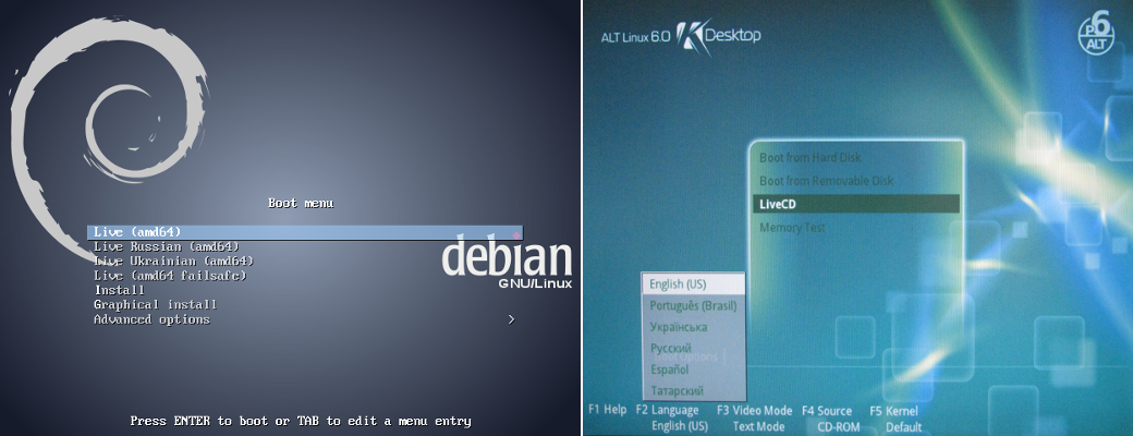
Fig. 6.3.2. Live disk's language selection menu Debian, ALTLinux.
As a result of booting from the live disc, you'll get a desktop of the TDE (Fig.6.3.3).
Fig. 6.3.3. Live disk's working desktop.
6.4. General provisions of the working conception with violations, alarms and notifications
Alarms and their processing in OpenSCADA is implemented in two ways, which is associated with the OpenSCADA structure, ways of its usage, as well as with the nature of alarms.The first part of alarms, with which the OpenSCADA works initially, and which is most needed, is notifications in various ways. Since the notification is part of the visualization interface, they are implemented in the VCA engine UI.VCAEngine and in the visualizers UI.Vision, UI.WebVision. Currently, notifications and alarms OpenSCADA subsystem implements the following functions:
- Notification:
- Light blinking of the object, the signaling group, the general status with the alarm color.
- Sound playing the sound file, or speech synthesis from text, associated with the alarm;
- Beep a continuous signal to the system, "Beeper", regardless of the alarm.
- Quittance of the alarm notification:
- Full by clicking on the colored blinking circle of the alarm status (the "ws_alarmLev" event), bottom right:
- By the notification way separate the light (the event "ws_alarmLight"), sound (event "ws_alarmSound") and the beep (the event "ws_alarmAlarm"), by pressing a button with the corresponding image, bottom right, or under the buttons of display options;
- By the alarm object to the visual presentation image it can be added the quittance command of the notification directly by itself;
- Alternately with listening it is character of the sound notification, because every alarm object can provide its own sound notification or the speech synthesis.
During the implementation of the notifications in the visualization area there is no direct rule for the formation of alarm sign because in many situations there is no uniqueness. Currently, on the side of the typified data source templates, it is practiced a method of the formation an "err" error attribute with the code and text of the alarm, and their processing and the formation of notification is made in the visual image of the data object. Sometimes the processing the parameter's borders is made directly in the visual image of the data object.
Subsequently, it became necessary to log and record the actual alarms for the current moment. For the alarms logging it is sufficient the formation of system messages with the specified category and message format, but for the monitoring the ongoing(actual) alarms a buffer is needed. Subsequently, a buffer was added as an add-on of the messages subsystem, and its addressing is made by the inversion of the message level. So, the message record with the level "-2" and the category "TEST" will put the message into the alarm buffer and duplicate it in the messages archive, with the level of "2". At the messages request with the negative level they will be taken from the alarm buffer. Deleting/removing of the alarm is made by writing the messages with the same category "TEST" and the non-negative level.
This concept of accounting the actual alarms allows you to use standard mechanisms for the messages processing to account the alarms:
- Alarm registration: SYS.message("alCategory", -3, "Parameter: alarm");
- Removing of the alarm: SYS.message("alCategory", 1, "Parameter: normal");
- Creating a list of actual (active) alarms by means of the "Protocol" or "Document" elements with the "-1" negative level for all.
Messages registration is best done on the side of the typified data source templates by a special function SYS.DAQ["Modul"]["Controller"].alarmSet(string mess, int lev = -5, string prm = ""), which unifies the category. To call this function from the context of the template you need to add "this" IO of the "Object" type, then the set of the alarm would be of the following form
this.cntr().alarmSet("Parameter: alarm", -5, "prm");. This function is now used in many data sources modules to account the global alarms of the controllers objects. The function creates the alarm with the category: al{ModId}:{CntrId}[.{PrmId}], where:
- ModId module's ID;
- CntrId controller's ID;
- PrmId parameter's ID from the prm argument.
6.5. Modified data storing/restoring into the logic level sources/wrappers
Sometime you can be to need for store and next restore, mostly in restart, some modified data like a hardware working time counters. At all like data source's and hardware's processing you need perform into the logic level of the subsystem DAQ. The task you can do in more ways means storing the data and next it's restoring to some storage but most known ways are:- Periodical the template parameter's context saving by the OpenSCADA user API request through cntrReq():
- If the counter template's attribute is under archiving/historying then you can the last value take from the archive/history at the template start, like that:
- Create some specific DB table and write/read the data direct to the table by the SQL-requests through SQLReq().
6.6. Debugging
If you strongly follow the main instruction, you won't encounter here any problems but if you make some doings for self, you may need also for some debugging for them. OpenSCADA provides wide possibilities to debug and observation for problems of programming into OpenSCADA of the regular user's space and for problems into same OpenSCADA and its parts.Generic approaches for user space debugging, allowed for both LTS and Work versions, mean:
- External attributes creation to see for the interim values and to observe for the current execution context.
- Debug messages creation to see also for the interim values and to observe for the execution sequence.
The present debugging mechanisms were expanded into the Work version in the way:
- User control for debugging by debug messages category, for the OpenSCADA parts and messages of the user space.
- Specific debugging and diagnostic environment for some parts of OpenSCADA, that is: DAQ sources (controller objects) and VCA interfaces (VCA projects).
Current execution context debugging
The debugging method means observing for the execution context by values of the variables, interim values appending include for more details.Current execution context of DAQ procedures you can observe into a proper page of the object of the execution context, like: the tab "Attributes" of the Logic Level parameter (Fig. 6.6.1), the tab "Calculation" of the Java-like based calculator (Fig. 6.6.2) and so on. To append some interim values you can temporary append (or set as an read-only attribute) and link some attributes to the template or append and link some IO to the function.
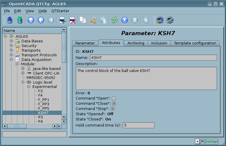
Fig. 6.6.1. The tab "Attributes" of the Logic Level parameter
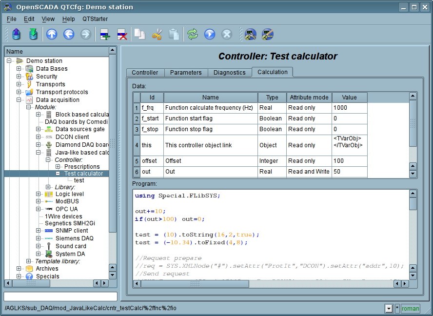
Fig. 6.6.2. The tab "Calculation" of the Java-like based calculator.
Current execution context of the VCA procedures (procedures of the widgets) you can observe on the tab "Attributes" of the proper page or widget of the session of the executed now project (Fig. 6.6.3). To append some interim values you can temporary append and link some attributes to the widget/page.
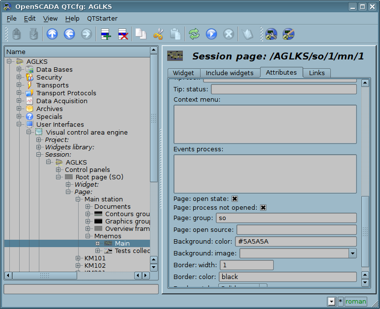
Fig. 6.6.3. The tab "Attributes" of the page or widget of the session of the executed now project.
Execution sequence debugging
The debugging methods means placing and/or enabling debugging messages and next its observing into the generic messages' archiving and observing interface (Fig. 6.6.4) or into the interface proper to the OpenSCADA part:- The tab "Diagnostics" of the controller's object of the data source (Fig. 6.6.5).
- The tab "Diagnostics" of the project's object of VCA into the configurator (Fig. 6.6.6) or of the project's properties of the development mode of UI.Vision (Fig. 6.6.7).
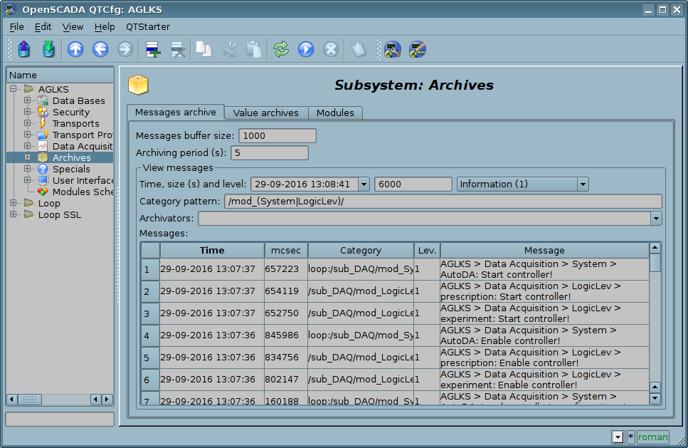
Fig. 6.6.4. The generic messages archiving and observing interface.
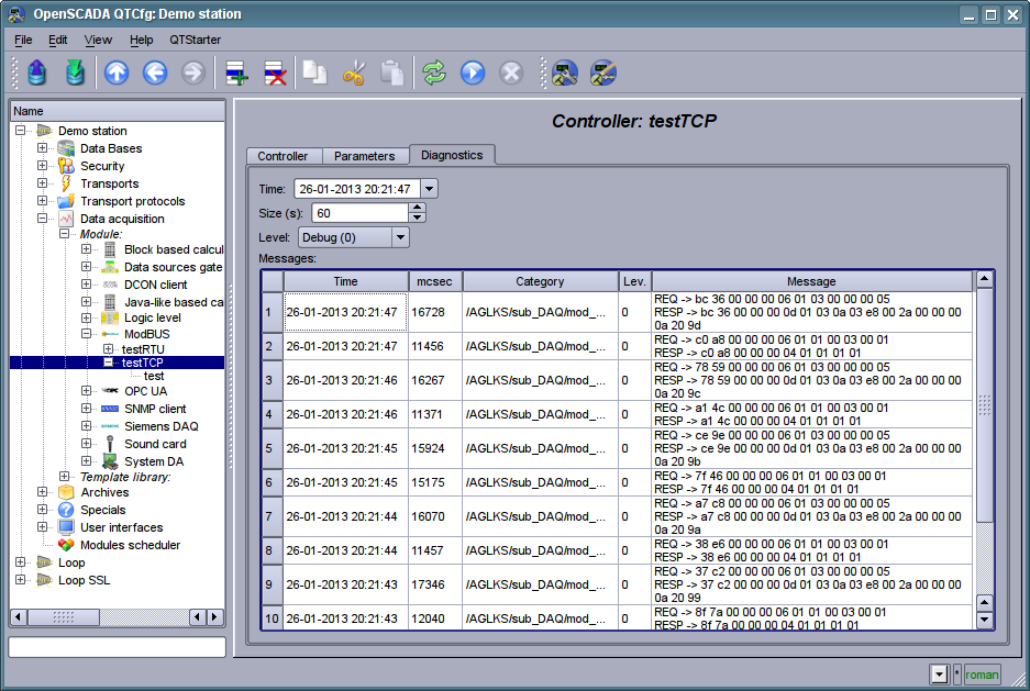
Fig. 6.6.5. The tab "Diagnostics" of the controller's object of the data source.
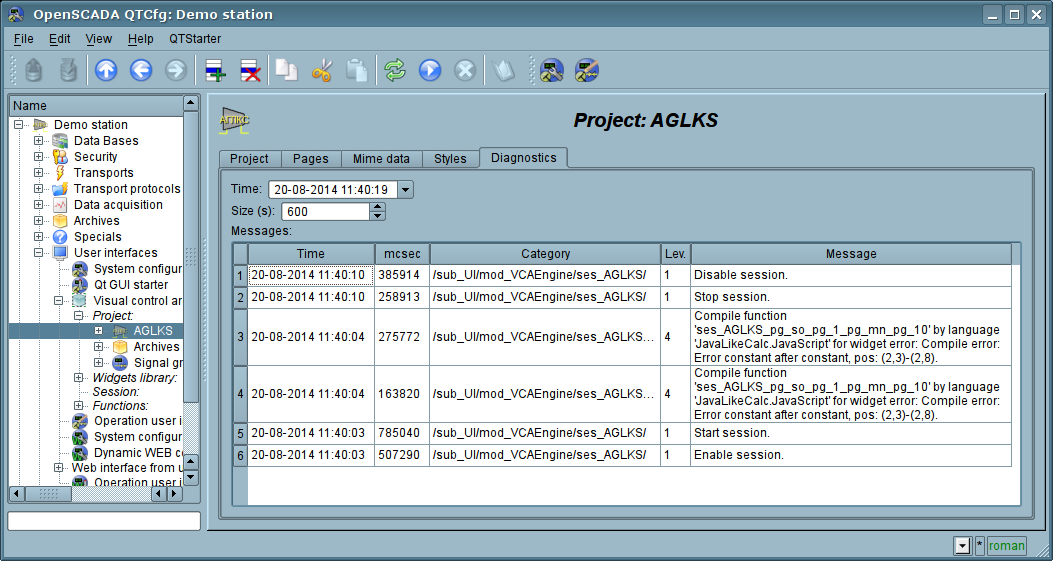
Fig. 6.6.6. The tab "Diagnostics" of the project's object of VCA into the configurator.
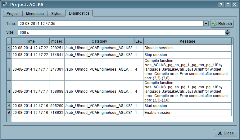
Fig. 6.6.7. The tab "Diagnostics" of the project's properties of the development mode of UI.Vision.
To append debug or other level's messages to self procedures you can use next functions:
- Generic: SYS.message(), SYS.mess{Debug,Info,Note,Warning,Err,Crit,Alert,Emerg}() To form generic messages with a custom category, then them mostly allowed to observe from the generic messages archiving and observing interface (Fig. 6.6.4).
- Generic: SYS.*.messSys() To form the system messages with the node path as a category and with the human readable path before the message. The messages will be allowed to observe into the diagnostics interface proper to the OpenSCADA part (Fig. 6.6.5, 6.6.6, 6.6.7).
- VCA: this.mess{Debug,Info,Note,Warning,Err,Crit,Alert,Emerg}() To form the system message with the category as the widget path. The messages will be allowed to observe into the VCA diagnostics interface (Fig. 6.6.6, 6.6.7).
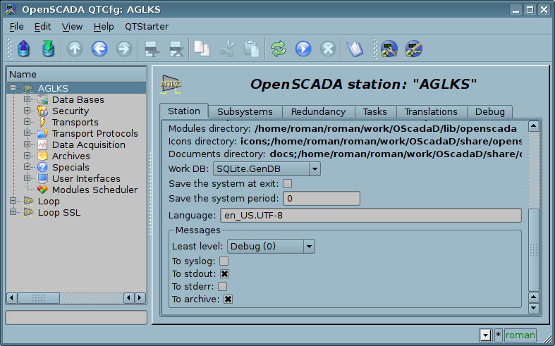
Fig. 6.6.8. The field "Least level" set to "Debug (0)".
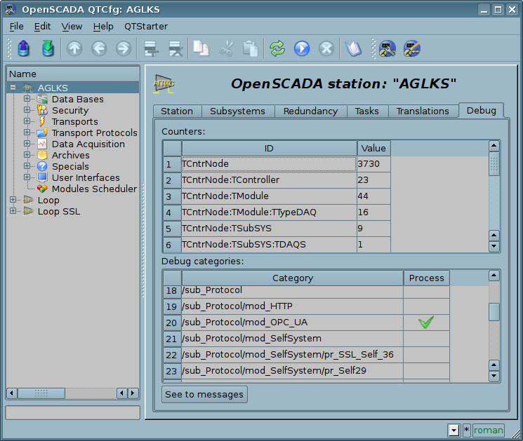
Fig. 6.6.9. The debug messages checking to debug.