Dynamic model of steam boiler #9 DMK
| Name: ModelKotelDMK Founded: January 2007 Version: 1.0.0 State: Finished, August 2010 Participants: Lysenko Maxim, Savochenko Roman, Yashina Ksenia Description: The project targets for creation full dynamic model steam boiler #9 Dnepr Metallurgical Combine (DMC). Address: DB in file: dmkkotel9.tlz | 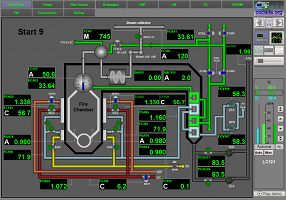 |
Introduction
The modelling object for the project, for creation full-scale dynamic model of real time, is multi-fuel steam boiler Dnepr Metallurgical Cobine (DMC) #9. A distinctive feature of the boiler is his multi-fuel nature and by that follow features in optimal control for boiler loading.
1 Targeting
Functionality, the development targeted for creation the real time model of multi-fuel boiler DMC.
Exploitation target the development is:
- ASC TP control algorithms testing;
- SCADA-system adequate algorithm functionality testing;
- Technological personal training.
2 Development
With targets acceleration, using early developments experience, and also for perfecting the technologies and tools for creation full dynamic models real time decided the model build into open SCADA system OpenSCADA environment. System OpenSCADA has mostly powerful mechanism for user side programming, and also has achievements for creation full dynamic real time models, which allow fast creation big dynamic models real time. Detailed about this has been discussed in ![]() report (RU), at
report (RU), at ![]() 5 Ukrainian conference of developers and users free software.
5 Ukrainian conference of developers and users free software.
2.1 Technological process
Before the Boiler model creation has been forming schematic diagram of the technological process, based on schematic diagram real technological process. Obtained diagram painted at Fig.1.
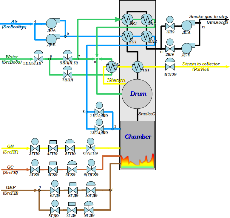
Fig. 1. The boiler DMK #9 technological scheme.
2.2 Modeling
For the technological process model forming based on allowed apparatus models has been direct used source schematic diagram and block calculator (BlockCalc) of system OpenSCADA. The apparatus models of the schematic diagram was appending to block scheme in accordance with the schematic diagram. Part new blocks has been added for auxiliary devices, and also flow's nodes. Node's block numbers set on schematic diagram by numbers about the flow's nodes.
The model made in view two block schemes by block calculator. Content and properties of the block schemes allowed into table 1.
Table 1. The model's block schemes
| ID | Name | Target | Execution period (ms) | Execution time at Athlon 64 3000+ (ms) |
| kotel9 | DMC Boiler9 | Contained Boiler #9 model of Dnepr Metallurgical Combine. | 5 | 1.1 |
| kotel9_cntr | DMC Boiler9 Controller | Contained control system Boiler #9 model of Dnepr Metallurgical Combine. | 1000 | 0.05 |
From the block schemes properties you can see, resource intensity at whole to central processor Athlon 64 3000+ (2000MHz) is 22%.
In table 2 allow used apparatus models list in accordance with schematic diagram.
Table 2. Used apparatus models
| Apparatus model | Devices (model blocks) |
| Library "Technological devices (DAQ.JavaLikeCalc.techApp)" | |
| Boiler: barrel (boilerBarrel) | kotel9.Áàðàáàí |
| Boiler: burner (boilerBurner) | kotel9.Òîïêà |
| Gas compressor (compressor) | kotel9.ÄÑÀ, kotel9.ÄÑÁ, kotel9.ÄÂÀ, kotel9.ÄÂÁ |
| Heat exchanger (heatExch) | kotel9.ÏÏ, kotel9.ÂÏ1, kotel9.ÂÏ2, kotel9.ÑÏ, kotel9.ÝÊ1, kotel9.ÝÊ2 |
| Valve (klap) | kotel9.3ÂÏ, kotel9.5ÂÏ, kotel9.7ÂÏ, kotel9.5ÃÄ9, kotel9.6ÃÄ9, kotel9.7ÃÄ9, kotel9.8ÃÄ9, kotel9.9ÃÄ9, kotel9.10ÃÄ9, kotel9.3ÃÊ9, kotel9.4ÃÊ9, kotel9.6ÃÊ9, kotel9.5ÃÊ9, kotel9.3ÃÏ9, kotel9.4ÃÏ9, kotel9.5ÃÏ9, kotel9.6ÃÏ9, kotel9.4ÃÏÇ9, kotel9.1Ø9, kotel9.2Ø9, kotel9.11Ø9, kotel9.13Ø9 |
| Network (loading) (net) | kotel9.ParNet, kotel9.Àòìîñô |
| Pipe 1->2 (pipe1_2) | kotel9.ÓÇ3, kotel9.Óç5, kotel9.Óç6, kotel9.Óç7, kotel9.Óç10 |
| Pipe 2->1 (pipe2_1) | kotel9.ÓÇ1, kotel9.ÓÇ2, kotel9.ÓÇ9, kotel9.Óç12 |
| Pipe 3->1 (pipe3_1) | kotel9.Óç8 |
| Source (pressure) (src_press) | kotel9.SrcÃÄ, kotel9.SrcÃÊ, kotel9.SrcÂîäà, kotel9.SrcÏÃ, kotel9.SrcÂîçäóõ |
| Library "Complex1 functions lib (Special.FLibComplex1)" | |
| PID regulator (pid) | kotel9_cntr.TCA1, kotel9_cntr.F_air_gas, kotel9_cntr.QAC151, kotel9_cntr.LC121, kotel9_cntr.PCA51, kotel9_cntr.FC101, kotel9_cntr.FC102, kotel9_cntr.FC103, kotel9_cntr.FC104, kotel9_cntr.FC105, kotel9_cntr.PSA76 |
| Library "Boiler Ê9" (DAQ.JavaLikeCalc.k9) | |
| Divider (Delitel) | kotel9_cntr.Air_Gas |
| Total fuel flow in boiler (Fsum) | kotel9_cntr.Fsum |
| Inversion (Inversion) | kotel9_cntr.5VP_inv |
Through the library apparatus models and the dynamic models build conception has been obtained the dynamic model, from that can get parameters into any point the schematic diagram both for the study and control algorithms for testing.
For getting the information about the technological process has been created TP parameters (table 3), which allow data from selected model's nodes.
Table 3. Technological process parameters
| Cipher | Description | Properties | Source |
| DMC Boiler9 (BlockCalc.kotel9) | |||
| LC121 | The water level in the boiler's drum | Áàðàáàí.Lo | |
| LÑA122, LSA124 | The level of water in a clean drum slot, right | %, (0;100), Precision 0 | Áàðàáàí.Lo |
| LSA123 | The level of water in a clean drum slot, left | %, (0;100), Precision 0 | Áàðàáàí.Lo |
| LCVG121 | 3FWL-9 position | %, (0;100), Precision 0 | 3ÂÏ.l_kl1 |
| LCVG122 | 3FWR-9 position | %, (0;100), Precision 0 | 3ÂÏ.l_kl2 |
| G_11SH | 11G-9 position | 11Ø9.l_kl1 | |
| G_12SH | 12G-9 position | 11Ø9.l_kl2 | |
| G_13SH | 13G-9 position | 13Ø9.l_kl1 | |
| G_14SH | 14G-9 position | 13Ø9.l_kl2 | |
| P_5VP | 5FW(1) position | 5ÂÏ.l_kl1 | |
| P_5VP_2 | 5FW(2) position | 5ÂÏ.l_kl2 | |
| P_7VP | 7FW position | 7ÂÏ.l_kl1 | |
| P_4GP9 | 4GN9 position | 4ÃÏ9.l_kl1 | |
| P_5GP9 | 5GN9 position | 5ÃÏ9.l_kl1 | |
| P_7GD | 7GBF position | 7ÃÄ9.l_kl1 | |
| P_8GD | 8GBF position | 8ÃÄ9.l_kl1 | |
| FCVG102 | 5GN-9 position | 5ÃÏ9.l_kl1 | |
| FCVG103 | 7GBF9 position | 7ÃÄ9.l_kl1 | |
| FCVG104 | 8GN-9 position | 8ÃÄ9.l_kl1 | |
| FCVG105 | 4GC-9 position | 4ÃÊ9.l_kl1 | |
| TCVG1_1 | 7FW-9 position | 7ÂÏ9.l_kl1 | |
| TCVG1_2 | 5FWL-9 position | 5ÂÏ9.l_kl1 | |
| PCVG76 | SEA productivity | rpm, (0;100), Precision 1 | ÄÑÀ.N |
| PCVG77 | SEB productivity | rpm, (0;100), Precision 1 | ÄÑÁ.N |
| FCV106 | BFA productivity | rpm, (0;100), Precision 1 | ÄÂÀ.N |
| FCV107 | BFB productivity | rpm, (0;100), Precision 1 | ÄÂÁ.N |
| PCA51 | Steam pressure after the MSV | at, (0;50), Precision 2 | 4ÃÏÇ9.Po |
| PSA52 | Steam pressure in the the boiler's drum | at, (0;40), Precision 2 | Áàðàáàí.Po1 |
| PCA52 | Steam pressure in the boiler's drum | at, (0;50), Precision 2 | Áàðàáàí.Po1 |
| PSA52_1 | Steam pressure in the boiler's drum | at, (0;40), Precision 2 | Áàðàáàí.Po1 |
| PSA53 | GN pressure before the regulating valve | at, (0;40), Precision 2 | 3ÃÏ9.Po |
| PSA53_1 | GN pressure before the diaphragm | at, (0;40), Precision 2 | 3ÃÏ9.Po |
| PSA53_2 | GN pressure before the diaphragm | at, (0;40), Precision 2 | 3ÃÏ9.Po |
| PSA54 | GN pressure after the regulating valve | at, (0;1.5), Precision 3 | 5ÃÏ9.Po |
| PA55 | GN pressure before the left burner | at, (0;40), Precision 2 | 6ÃÏ9.Po |
| PA56 | GN pressure before the right burner | at, (0;40), Precision 2 | 6ÃÏ9.Po |
| PSA57_1, PSA57_2 | GBF pressure on the general pipeline. | at, (0;2), Precision 2 | ÓÇ3.Pi |
| PSA59 | GBF pressure after valve on the left gas pipeline | at, (1;2), Precision 3 | 10ÃÄ9.Po |
| PSA60 | GBF pressure after valve on the right gas pipeline | at, (1;2), Precision 3 | 9ÃÄ9.Po |
| P61 | GBF pressure before the left burner | at, (0;1.6), Precision 2 | 9ÃÄ9.Po |
| P62 | GBF pressure before the right burner | at, (0;1.6), Precision 2 | 10ÃÄ9.Po |
| PSA63_1 | GC pressure after 5GC-9 | at, (0;2), Precision 2 | 5ÃÊ9.Po |
| PSA63_2 | GC pressure after 3GC-9 | at, (0;2), Precision 2 | 3ÃÊ9.Po |
| PSA64 | GC pressure after the regulating valve | at, (0;2), Precision 3 | 4ÃÊ9.Po |
| P65 | GC pressure before the left burner | at, (0;1.6), Precision 2 | 6ÃÊ9.Po |
| P66 | GC pressure before the right burner | at, (0;1.6), Precision 2 | 6ÃÊ9.Po |
| P67 | The air pressure before the first stage of A/H to the left. | at, (0;1.2), Precision 2 | ÓÇ9.Po |
| P72 | The air pressure in the upper tier of the left burner | at, (0;1.2), Precision 2 | ÓÇ2.Po |
| P68 | The air pressure before the first stage of A/H to the right. | at, (0;1.2), Precision 2 | ÓÇ9.Po |
| PSA70 | Air pressure after the second stage of air-heater | at, (0;1.2), Precision 2 | ÂÏ2.Po2 |
| PSA71 | Air pressure after the second stage of air-heater | at, (0;1.2), Precision 2 | ÂÏ2.Po2 |
| P73, PSA73 | The air pressure in the upper tier of the right burner | at, (0;1.16), Precision 2 | ÓÇ2.Po |
| P74 | The air pressure on the lower tier of the left burner | at, (0;1.16), Precision 2 | ÓÇ2.Po |
| P75, PSA75 | The air pressure on the lower tier of the right burner | at, (0;1.16), Precision 2 | ÓÇ2.Po |
| PCSA76 | The vacuum in the fire chamber on the left | at, (0.9;1), Precision 3 | Òîïêà.Po |
| PCSA77 | The vacuum in the fire chamber on the right | at, (0.9;1), Precision 3 | Òîïêà.Po |
| P78 | The vacuum in front of "SE-A" | at, (0.9;1), Precision 2 | 1Ø9.Po |
| P79 | The vacuum in front of "SE-B" | at, (0.9;1), Precision 2 | 2Ø9.Po |
| PSA80 | FW pressure on the left feeding line | at, (0;60), Precision 2 | SrcÂîäà.Po |
| PSA81 | FW pressure on the right feeding line | at, (0;60), Precision 2 | SrcÂîäà.Po |
| PSA85 | Air pressure after the air heater | at, (0;2), Precision 3 | ÂÏ2.Po2 |
| P103 | GBF pressure on the diaphragm on the left | at, (0;2), Precision 2 | ÓÇ3.Po2 |
| P104 | GBF pressure on the diaphragm on the right | at, (0;2), Precision 2 | ÓÇ3.Po1 |
| Src_GP_Pi | The inlet pressure at the source of GN | SrcÏÃ.Pi | |
| P_GP_S | GN pressure after the source | SrcÏÃ.Po | |
| P_GP_4GP | GN pressure after 4GN9 | 4ÃÏ9.Po | |
| P_3VP_1 | 3FW9(1) position | 3ÂÏ.l_kl1 | |
| P_3GP9 | 3GN9 position | 3ÃÏ9.l_kl1 | |
| P_6GP9_1 | 6GN9_1 position | 6ÃÏ9.l_kl1 | |
| P_6GP9_2 | 6GN9_2 position | 6ÃÏ9.l_kl2 | |
| P_5GK | 5GC position | 5ÃÊ9.l_kl1 | |
| Pbar | The pressure in the boiler's drum | Áàðàáàí.Po1 | |
| TCA1 | Steam temperature after MSV | 4ÃÏÇ9.To | |
| F_3VP | Water flow after 3FW | 3ÂÏ.Fo | |
| F_5VP | Water flow after 5FW | 5ÂÏ.Fo | |
| F_7VP | Water flow after 7FW | 7ÂÏ.Fo | |
| Fbar | Water flow into the drum | Áàðàáàí.Fi1 | |
| F_UZ8 | Water flow after UZ8 | Óç8.Fo | |
| FC101 | Steam flow from boiler | t/h, (0;100), Precision 2 | 4ÃÏÇ9.Fo |
| FC102 | Flow of the natural gas after 3GN9 | 3ÃÏ9.Fo | |
| FC102_0 | Natural gas flow after it source | SrcÏÃ.Fo | |
| FC102_1 | Natural gas flow after 4GN9 | 4ÃÏ9.Fo | |
| FC102_2 | Natural gas flow after 5GN9 | 5ÃÏ9.Fo | |
| FC102_3 | Natural gas flow after 6GN9 | 6ÃÏ9.Fo | |
| FC103 | GBF flow on the left gas pipeline | 5ÃÄ9.Fi | |
| FC104 | GBF flow on the right gas pipeline | 6ÃÄ9.Fi | |
| FC105 | Flow of coke gas after 5GC9 | 5ÃÊ9.Fo | |
| FC106 | Air flow to the left burner | t/h, (0;100), Precision 1 | ÓÇ2.Fi1 |
| FC107 | Air flow to the right burner | t/h, (0;100), Precision 1 | ÓÇ2.Fi2 |
| FA108 | The flow of air-superheater on the right feeding line | t/h, (0;200), Precision 2 | SrcÂîäà.Fo |
| F109 | Water flow for the thermostat | t/h, (0;200), Precision 2 | 7ÂÏ.Fo |
| FA110 | The flow of air-superheater on the left feeding line | t/h, (0;200), Precision 2 | SrcÂîäà.Fo |
| QA151 | The oxygen content in FG after the superheater | %, (0;20), Precision 2 | Òîïêà.O2 |
| QA152 | The CO content in FG after the superheater | %, (0;20), Precision 2 | Òîïêà.CO |
| QA153 | Oxygen content in the exhaust FG | %, (0;20), Precision 2 | Òîïêà.O2 |
| T2 | Natural gas temperature | deg.K, (223;323), Precision 2 | 3ÃÏ9.To |
| T3 | GBF temperature | deg.K, (273;373), Precision 2 | 5ÃÄ9.Ti |
| T5 | The temperature of the GC before boiler | deg.K, (273;373), Precision 2 | 4ÃÊ9.To |
| T7 | Air temperature after the second stage of air-heater on the left | deg.K, (273;773), Precision 2 | ÂÏ2.To2 |
| T8 | Air temperature after the second stage of air-heater on the right | deg.K, (273;773), Precision 2 | ÂÏ2.To2 |
| T13 | FG temperature before superheater on the left | deg.K, (273;1027), Precision 2 | Áàðàáàí.To2 |
| T14 | FG temperature before superheater on the right | deg.K, (273;1027), Precision 2 | Áàðàáàí.To2 |
| T15 | FG temperature before 2 stage of economizer on the left | deg.K, (273;873), Precision 2 | ÏÏ.To1 |
| T16 | FG temperature before 2 stage of economizer on the right | deg.K, (273;873), Precision 2 | ÏÏ.To1 |
| T17 | FG temperature after 2 stage of economizer on the left | deg.K, (273;873), Precision 2 | ÝÊ2.To1 |
| T18 | FG temperature after 2 stage of economizer on the right | deg.K, (273;873), Precision 2 | ÝÊ2.To1 |
| T19 | FG temperature before the first stage of air-heater on the left | deg.K, (273;873), Precision 2 | ÝÊ1.To1 |
| T20 | FG temperature before the first stage of air-heater on the right | deg.K, (273;873), Precision 2 | ÝÊ1.To1 |
| T21 | FG temperature before the second stage of air-heater on the left | deg.K, (273;873), Precision 2 | ÝÊ2.To1 |
| T22 | FG temperature before the second stage of air-heater on the right | deg.K, (273;873), Precision 2 | ÝÊ2.To1 |
| T23 | FG temperature before 1 stage of economizer on the left | deg.K, (273;873), Precision 2 | ÂÏ2.To1 |
| T24 | FG temperature before 1 stage of economizer on the right | deg.K, (273;873), Precision 2 | ÂÏ2.To1 |
| TA25 | FG temperature before th "SE-A" | deg.K, (273;673), Precision 2 | 1Ø9.To |
| TA26 | FG temperature before th "SE-B" | deg.K, (273;673), Precision 2 | 2Ø9.To |
| T35 | The temperature of water on the left feeding line | deg.K, (273;473), Precision 2 | 3ÂÏ.To |
| T36 | The temperature of water on the right feeding line | deg.K, (273;473), Precision 2 | 3ÂÏ.To |
| T37 | The water temperature after the economizer on the left | deg.K, (273;673), Precision 2 | ÝÊ2.To2 |
| T38 | The water temperature after the economizer on the right | deg.K, (273;673), Precision 2 | ÝÊ2.To2 |
| DMC Boiler9 Controller (BlockCalc.kotel9_cntr) | |||
| TCA1 | Steam temperature at the outlet | K, (273;800), Precision 0 | TCA1.* |
| QAC151 | The percentage of oxygen in the flue gases. | %, (0;15), Precision 1 | QAC151.* |
| LC121 | Level in the boiler's drum | %, (0;100), Precision 1 | LC121.* |
| 5VP | %, (0;100), Precision 1 | 5VP_inv.OVar | |
| FC101 | Steam flow from the boiler | t/h, (0;150), Precision 0 | FC101.* |
| FC102 | Natural gas flow | t/h, (0;6), Precision 1 | FC102.* |
| FC103 | Flow of blast furnace gas on the left gas pipeline | t/h, (0;70), Precision 1 | FC103.* |
| FC104 | Flow of blast furnace gas on the right gas pipeline | t/h, (0;70), Precision 1 | FC104.* |
| FC105 | Flow of the coke oven gas | t/h, (0;10), Precision 1 | FC105.* |
| PSA76 | The vacuum in the fire chamber | at, (0.9;1), Precision 3 | PSA76.* |
2.3 Regulation
By itself, the dynamic model may be unstable without control. For example, drum level parameter have not self-regulation and gone to edge points at case balance miss into regulation parameters. By that reason and for create all-sufficient model, which capable for work autonomous and without PLC for regulation, has been created regulators controller object for the boiler model in accordance with regulation schemes on figures 2 - 4.
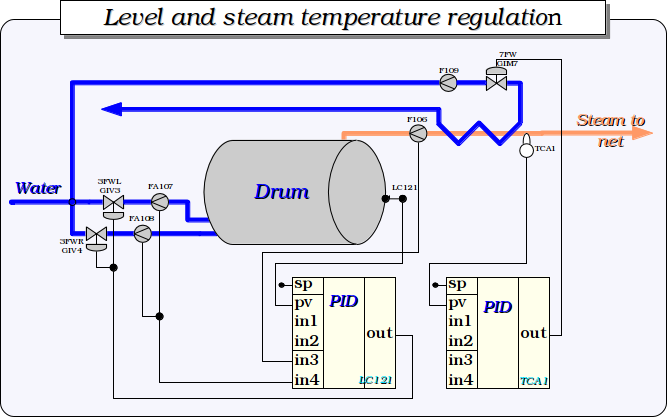
Fig. 2. Level and steam temperature regulation.
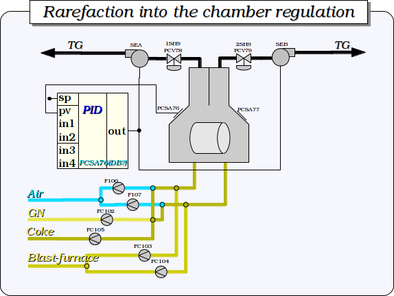
Fig. 3. Rarefaction into the chamber regulation.
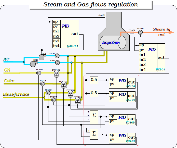
Fig. 4. Steam and Gas flows regulation.
3 User interface
The model user interface contain elven signal objects (Fig.5). Each signal object contain several mnemo, graphics group, contour group and overviews group.
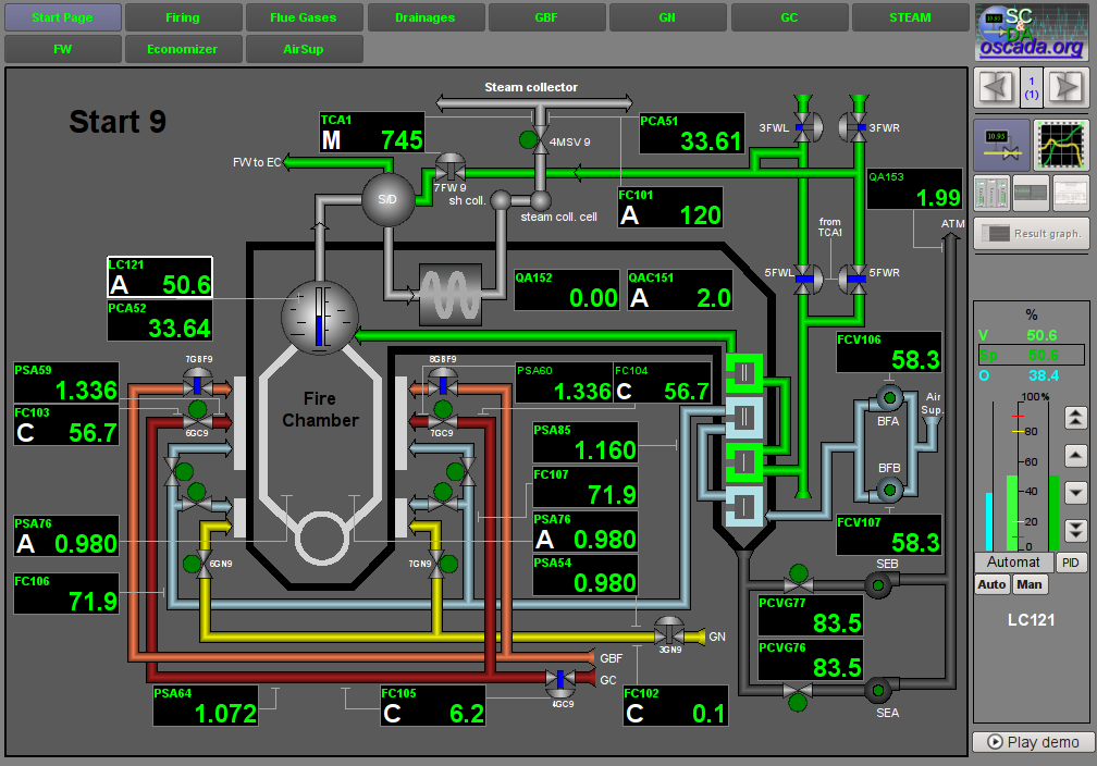
Fig. 5. User's interface generic view window.
3.1 Signal object "Start"
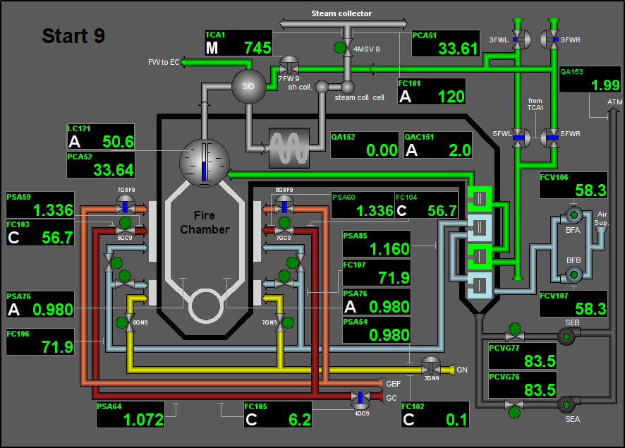
Fig. 6. Signal object "Start" mnemo.
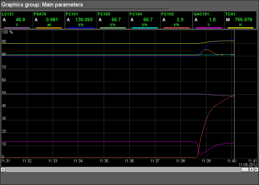
Fig. 7. Signal object "Start" graphics group.
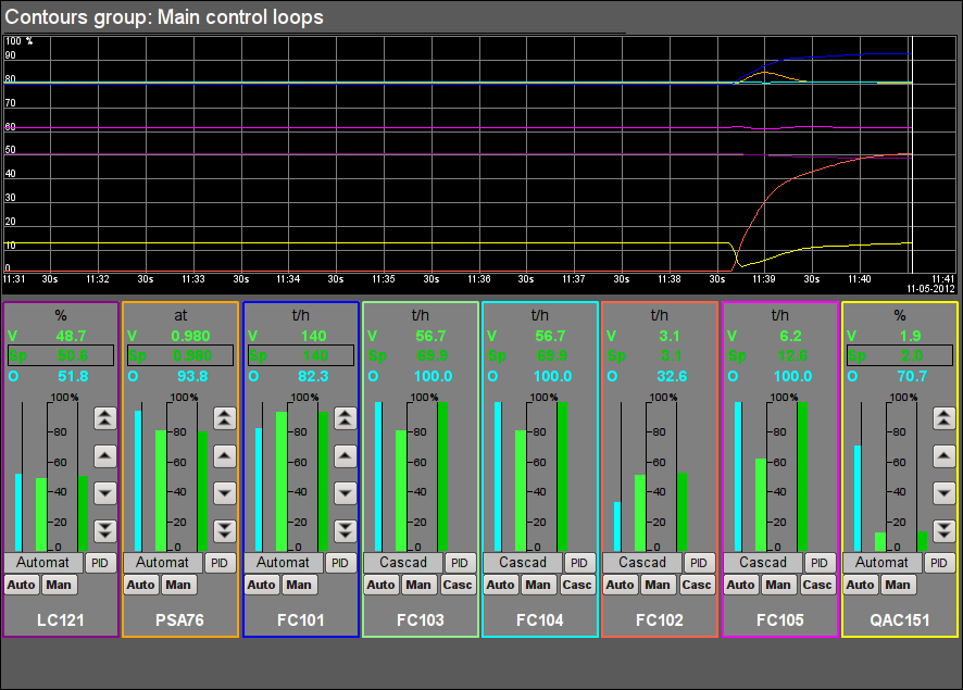
Fig. 8. Signal object "Start" contours group.
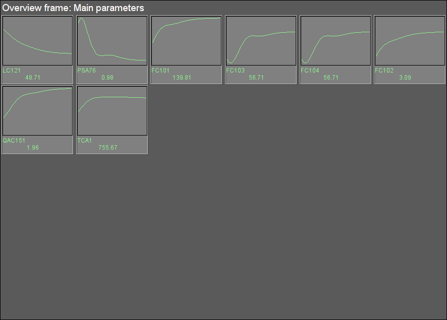
Fig. 9. Signal object "Start" overview group.
3.2 Signal object "Firing"
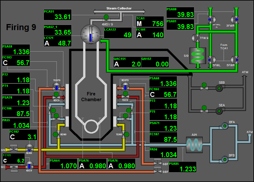
Fig. 10. Signal object "Firing" mnemo.
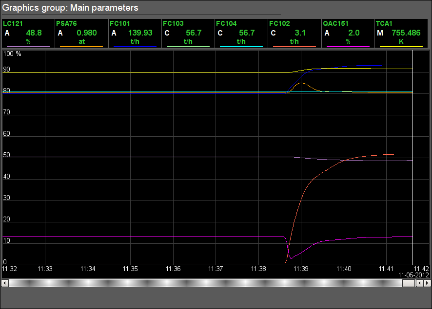
Fig. 11. Signal object "Firing" graphics group.
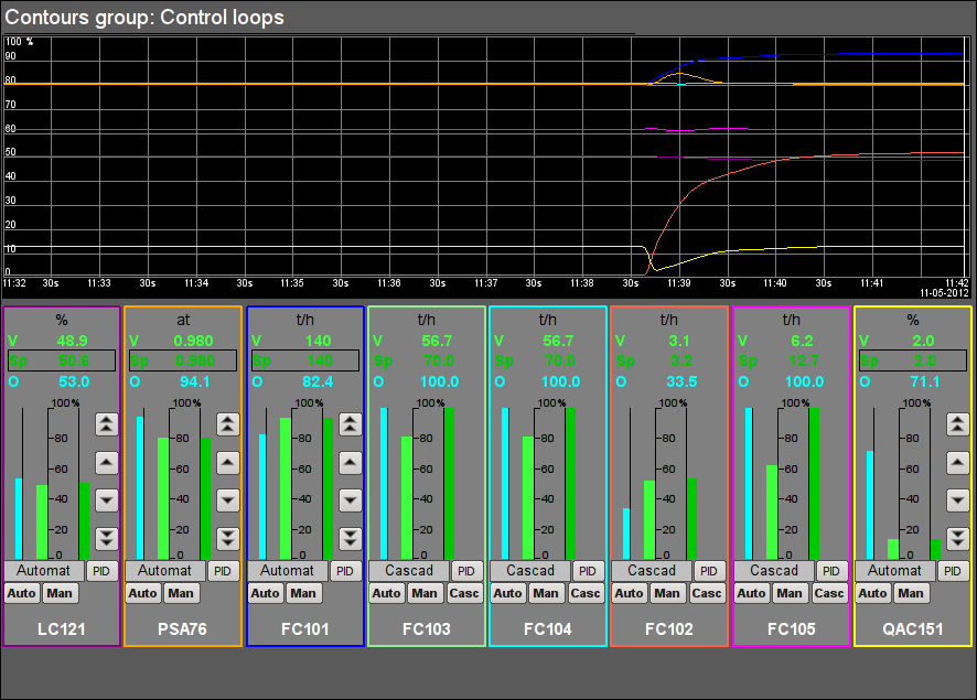
Fig. 12. Signal object "Firing" contour group.
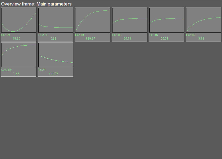
Fig. 13. Signal object "Firing" overview group.
3.3 Signal object "Flue Gases"
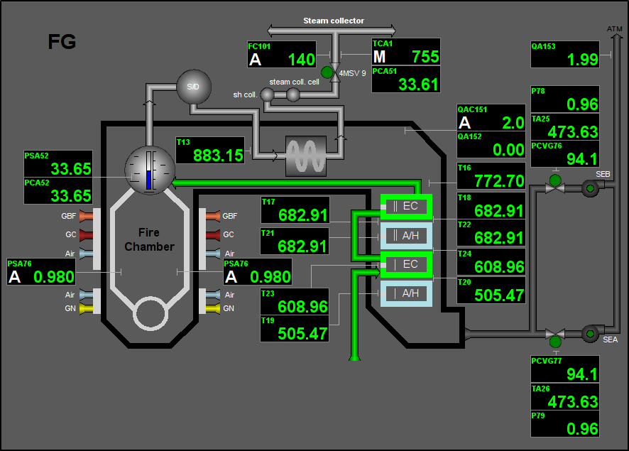
Fig. 14. Signal object "Flue Gases" mnemo.
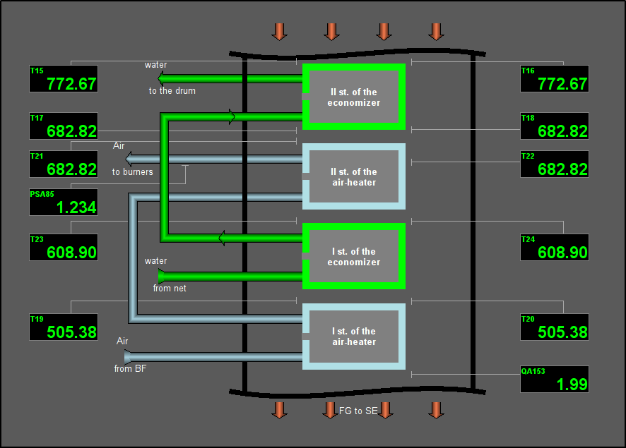
Fig. 15. Signal object "Flue Gases" mnemo 2.
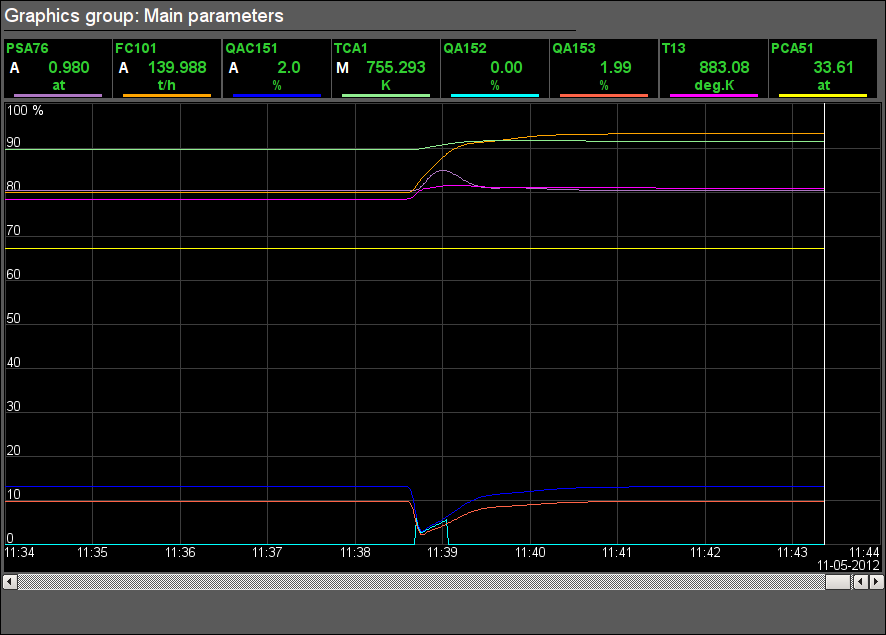
Fig. 16. Signal object "Flue Gases" graphics group.
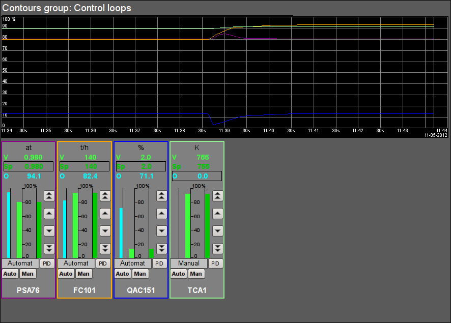
Fig. 17. Signal object "Flue Gases" contour group.
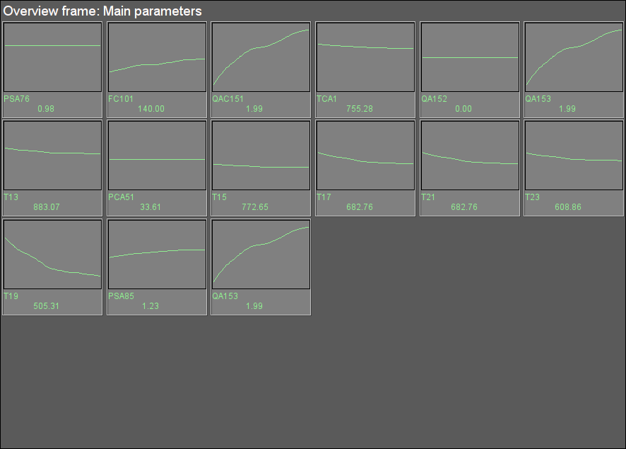
Fig. 18. Signal object "Flue Gases" overview group.
3.4 Signal object "Drainages"
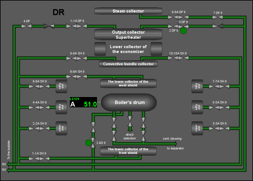
Fig. 19. Signal object "Drainages" mnemo.
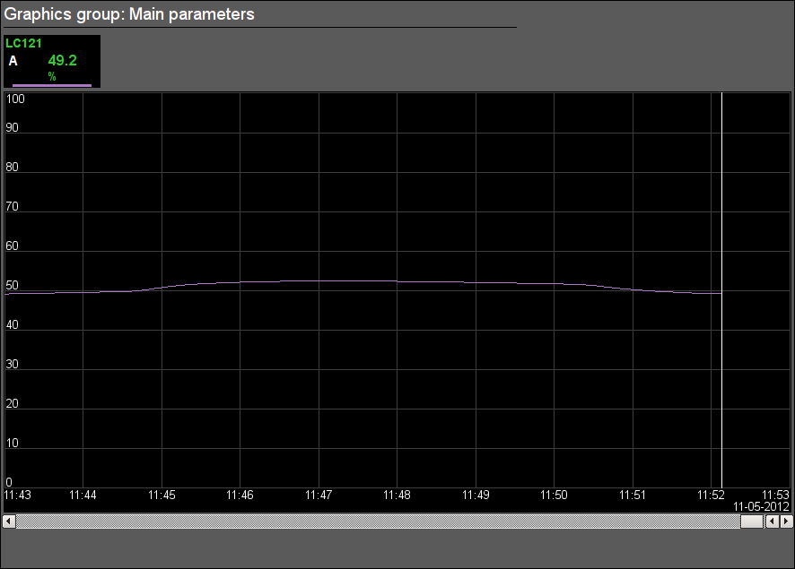
Fig. 20. Signal object "Drainages" graphics group.
Fig. 21. Signal object "Drainages" contour group.
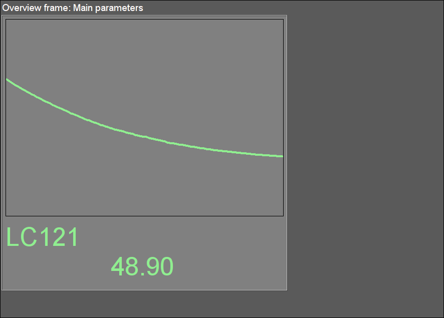
Fig. 22. Signal object "Drainages" overview group.
3.5 Signal object "GBF"
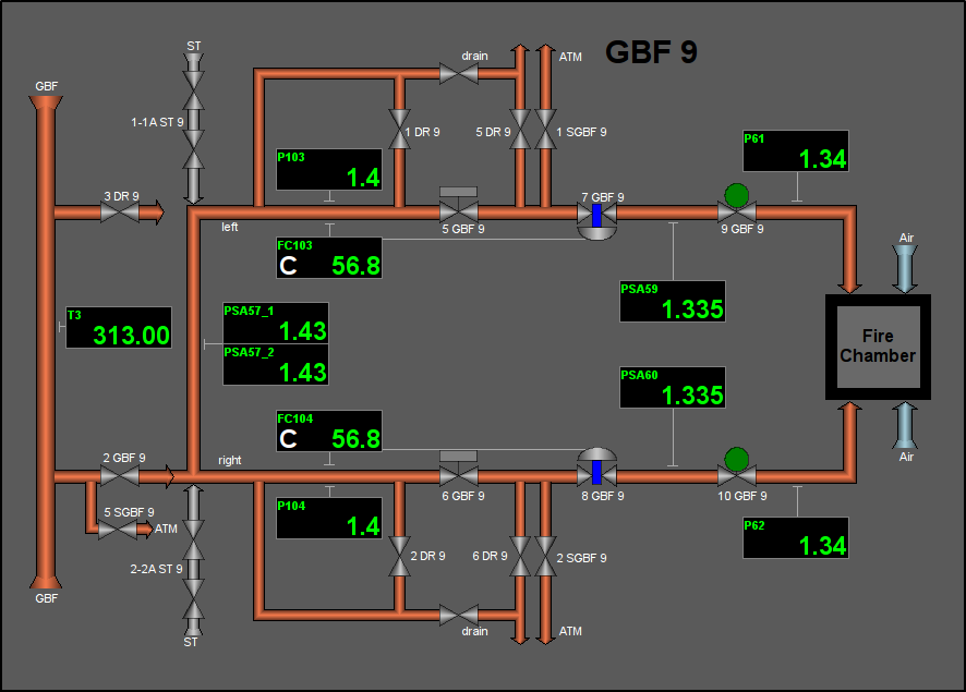
Fig. 23. Signal object "GBF" mnemo.
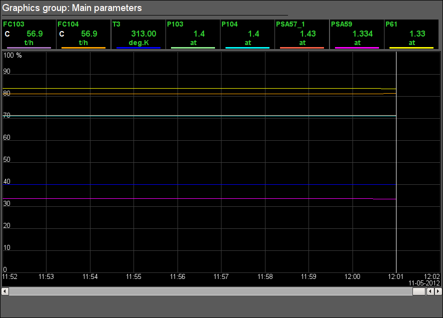
Fig. 24. Signal object "GBF" graphics group.
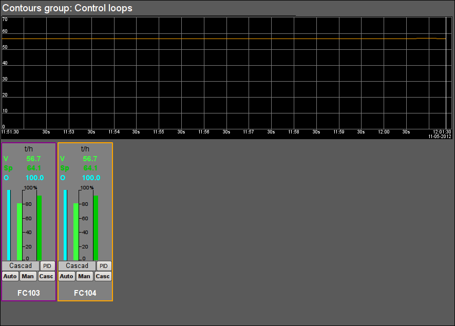
Fig. 25. Signal object "GBF" contour group.
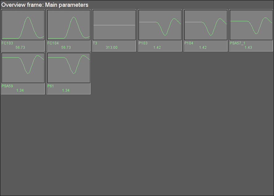
Fig. 26. Signal object "GBF" overview group.
3.6 Signal object "GN"
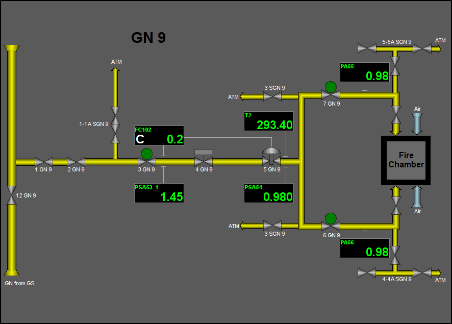
Fig. 27. Signal object "GN" mnemo.
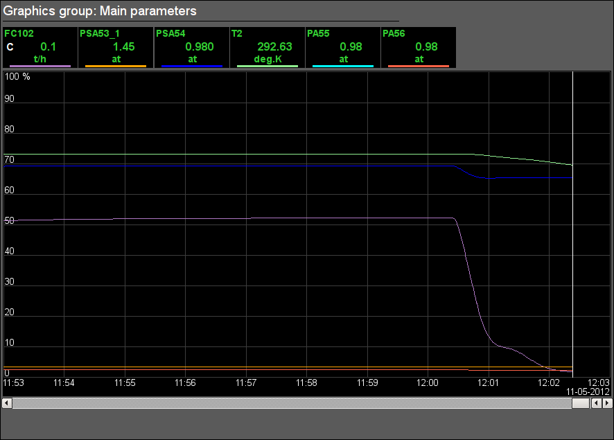
Fig. 28. Signal object "GN" graphics group.
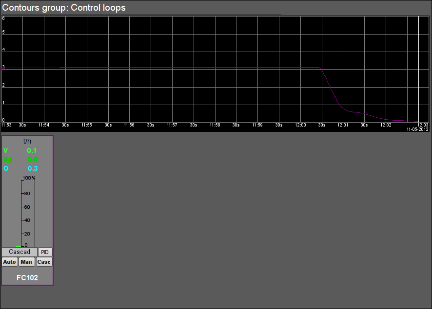
Fig. 29. Signal object "GN" contour group.
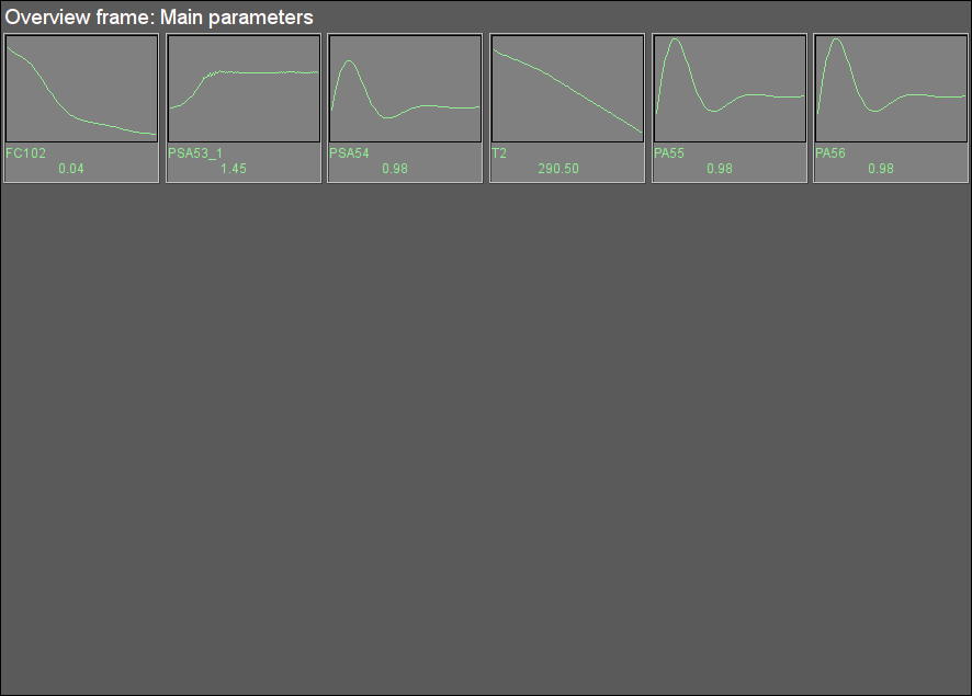
Fig. 30. Signal object "GN" overview group.
3.7 Signal object "GC"
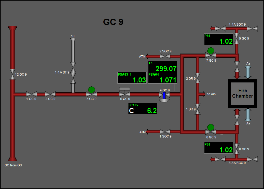
Fig. 31. Signal object "GC" mnemo.
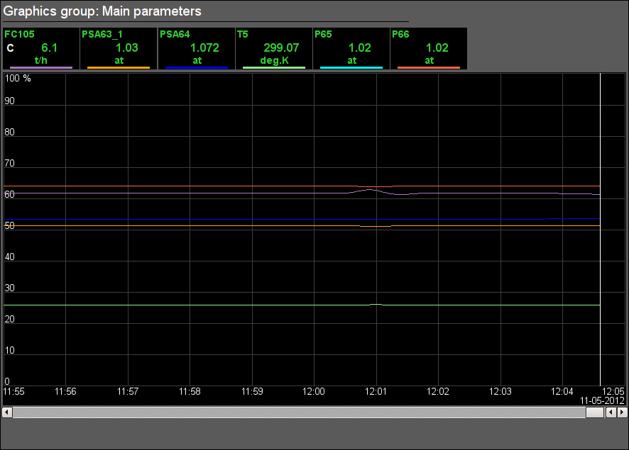
Fig. 32. Signal object "GC" graphics group.
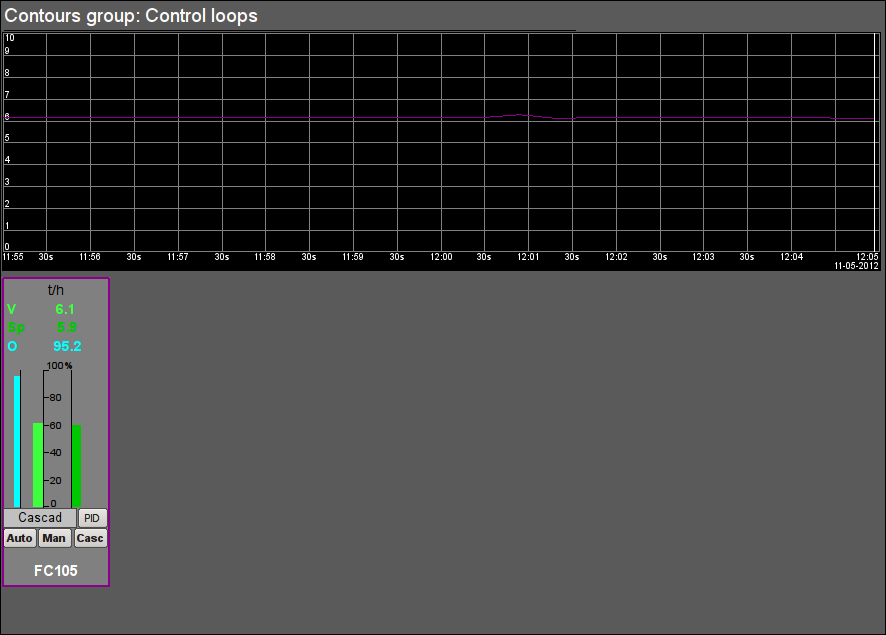
Fig. 33. Signal object "GC" contour group.
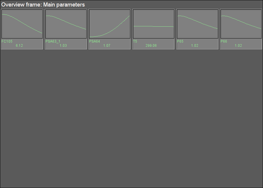
Fig. 34. Signal object "GC" overview group.
3.8 Signal object "STEAM"
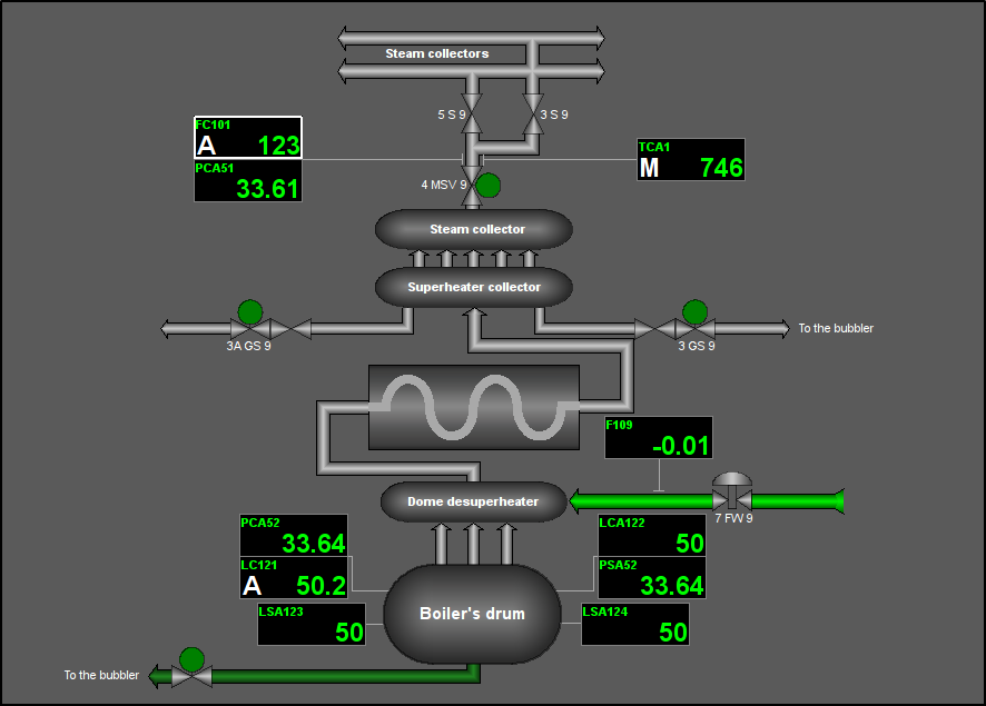
Fig. 35. Signal object "STEAM" mnemo.
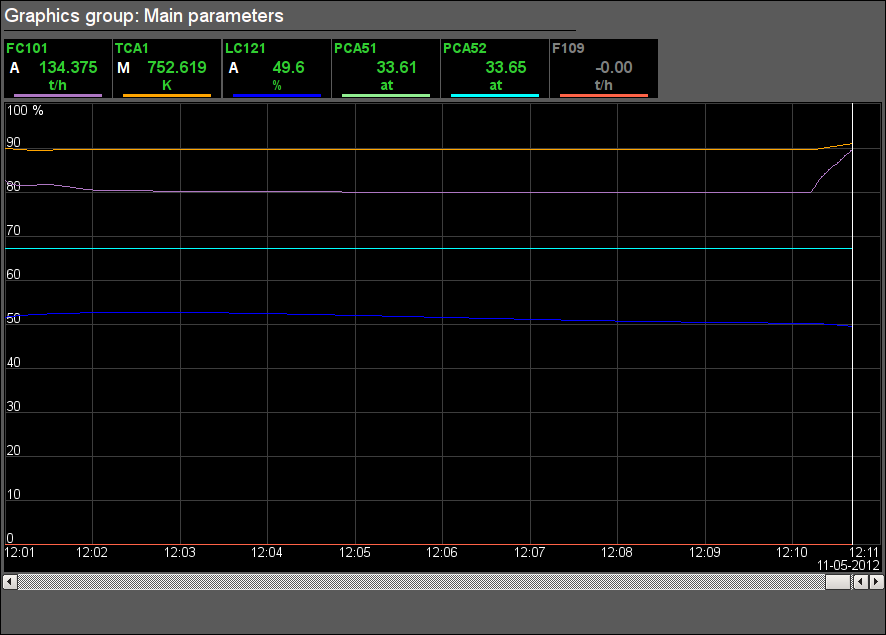
Fig. 36. Signal object "STEAM" graphics group.
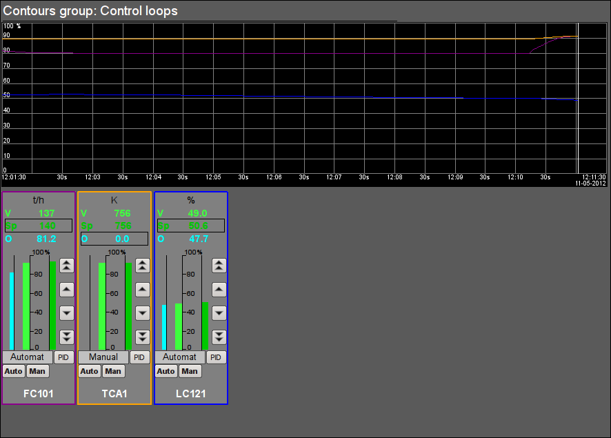
Fig. 37. Signal object "STEAM" contour group.
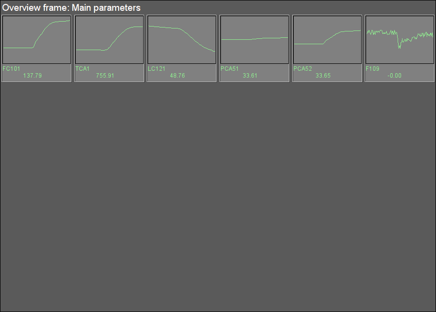
Fig. 38. Signal object "STEAM" overview group.
3.9 Signal object "FW"
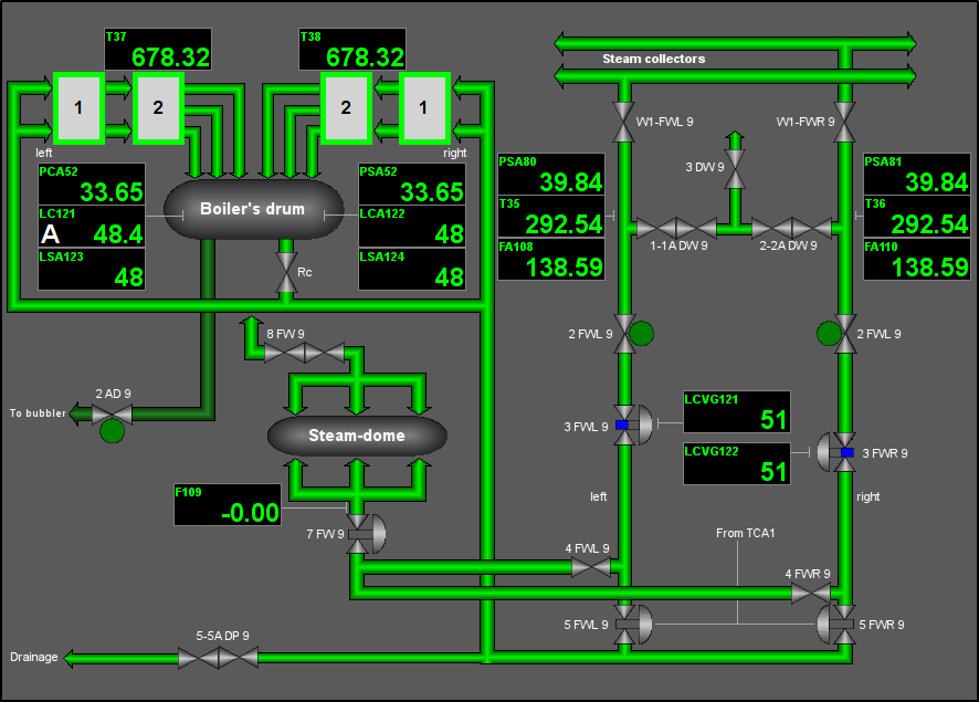
Fig. 39. Signal object "FW" mnemo.
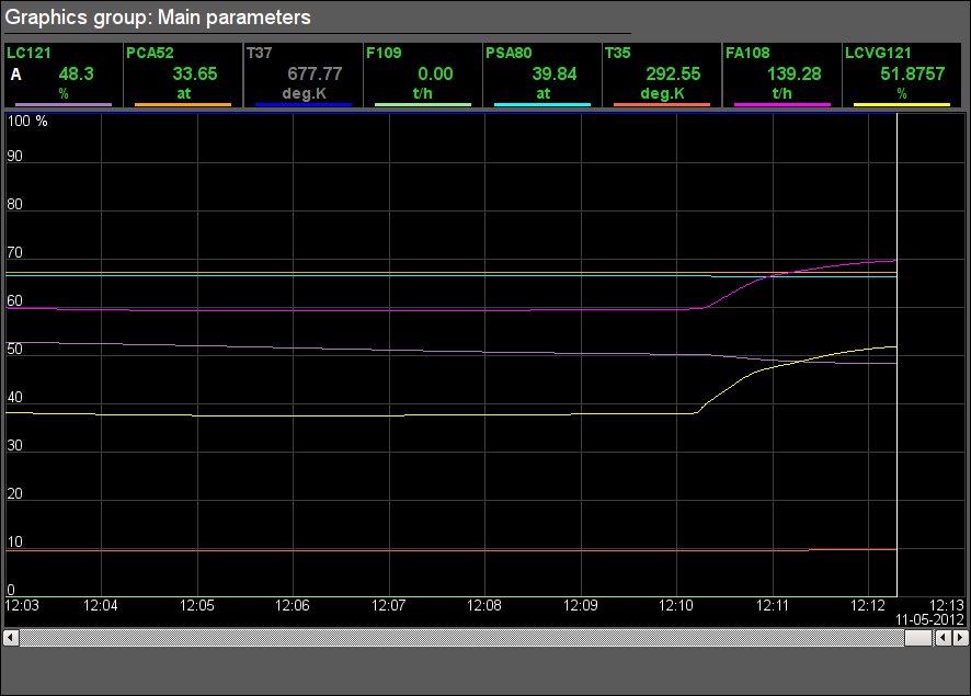
Fig. 40. Signal object "FW" graphics group.
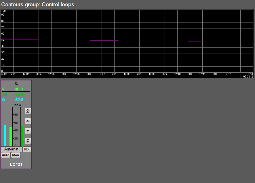
Fig. 41. Signal object "FW" contour group.
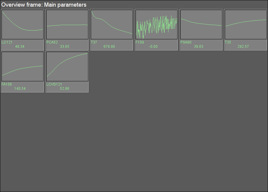
Fig. 42. Signal object "FW" overview group.
3.10 Signal object "Economizer"
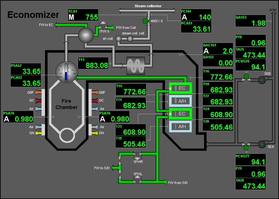
Fig. 43. Signal object "Economizer" mnemo.
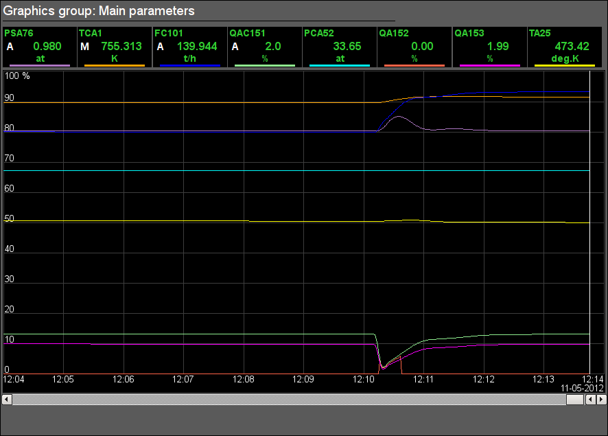
Fig. 44. Signal object "Economizer" graphics group.
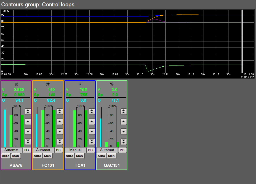
Fig. 45. Signal object "Economizer" contour group.
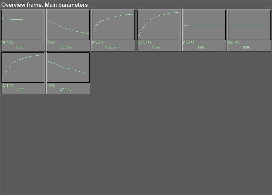
Fig. 46. Signal object "Economizer" overview group.
3.11 Signal object "AirSup"
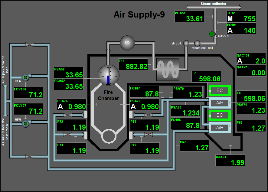
Fig. 47. Signal object "AirSup" mnemo.
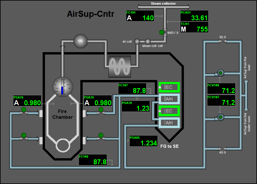
Fig. 48. Signal object "AirSup" mnemo 2.
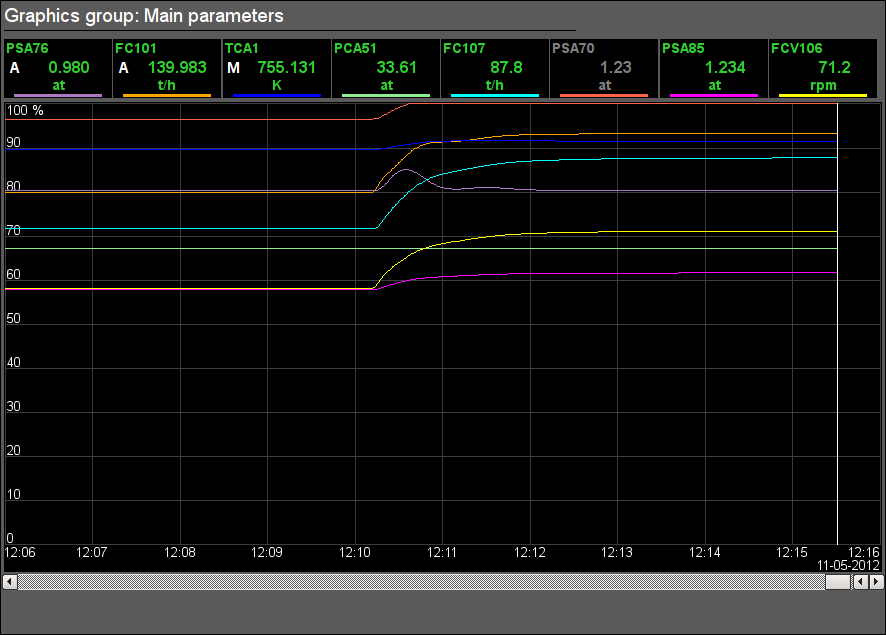
Fig. 49. Signal object "AirSup" graphics group.
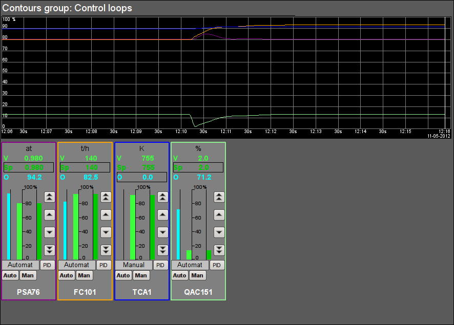
Fig. 50. Signal object "AirSup" contour group.
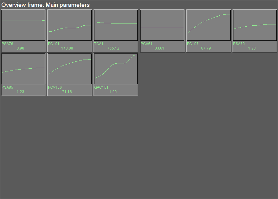
Fig. 51. Signal object "AirSup" overview group.
4 Results
The development results was full-featured dynamic model of multi-fuel steam boiler technological process for high pressure and productivity. The model is available at three languages and has been included to OpenSCADA-system distributives for demonstration functions and capabilities.
The model is allow control capability from operator face, include operation:
- regulators control:
- regulator mode change: "Automate", "Manual" and "Cascade";
- set need setpoint value or executive mechanism manual output;
- PID-regulator's parameters configuration.
In general, into control scheme, fully work next regulators:
- LC121 — level in the boiler's drum;
- PSA76 — the vacuum in the fire chamber;
- FC101 — steam flow from the boiler;
- FC102 — natural gas flow;
- FC103, FC104 — flow of blast furnace gas on the left gas pipeline ;
- FC105 — flow of the coke oven gas;
- QAC151 — the percentage of oxygen in the flue gases.;
- TCA1 — steam temperature at the outlet.
In applicable sense the model has been available tests algorithms for control several fuel types flows.
The model's resource intensity is 70% to CPU 800 MHz core, architecture x86.
Links