ACS of the ball drum mills BDM 287/410 of the boiler #7,8,9 of BKZ 160–100 PT
| Begin: 07(Jul) 2009 for BDM7,9; 26 06(Jun) 2015 for BDM8 Finish: 08(August) 2010 for BDM7,9; 22 12(December) 2015 for BDM8 Location: Kramatorsk city, CHP Customer: Limited liability company (Ltd) "Kramatorskteploenergo", Participants: Roman Savochenko, Maksim Lisenko (2009-2010), Description: Automation Control System (ACS) of loading two ball drum mills "BDM 287/410" of boilers №7, 8, 9 | ") |
1. Object of automation
In exploitation of Kramatorskteploenergo Ltd is a Central Heat Energy (CHM) in contains of five working boilers BKZ 160–100 PT (5, 6, 7, 8 and 9). The boilers produce steam with pressure 100 kgf/cm2 and nominal productivity up to 160 ton/hour. Produced steam transferred to turbines and heat carrier of Kramatorsk city. As fuel of the boilers use the coal dust and the natural gas, mostly for ignition and light. The primary coal is non-gas (anthracite) coals which is less explosive and allow to milling on temperatures up to 150°С. Boilers 6, 7, 8 and 9 have working system of the dust preparation, which the boilers supply by dust.
The dust preparation process includes: department of the coals preparation, the coals transporter to bunker of ball mills (SRC-Supply Raw Coal), two ball mills and the dust bunker. Subject of the project is automatic control of process of loading of the ball drum mills depends from their mode and load.
The company uses ball drum mills "BDM 287\410 PT". Functional scheme of a ball mill with the automation components is shown in Figure 1.
")
Fig. 1. Functional scheme of a ball mill.
2. ACS (Automatic Control System)
Structural scheme of the ACS of mills of single boiler (K8) is shown on the Figure 2, and Figure 3 (as a part of DIYA Ltd automation solutions and the common network), it is contains this nodes: two cabinets by controller CC 7, 8, 9 (on CHB — Central Heat Billboard) and CFC (into nonoperative contour of boiler 7, 8, 9); and the stations of automation workplace of operator AWP1 and AWP2.
")
Рис. 2. Structural scheme of the ACS.
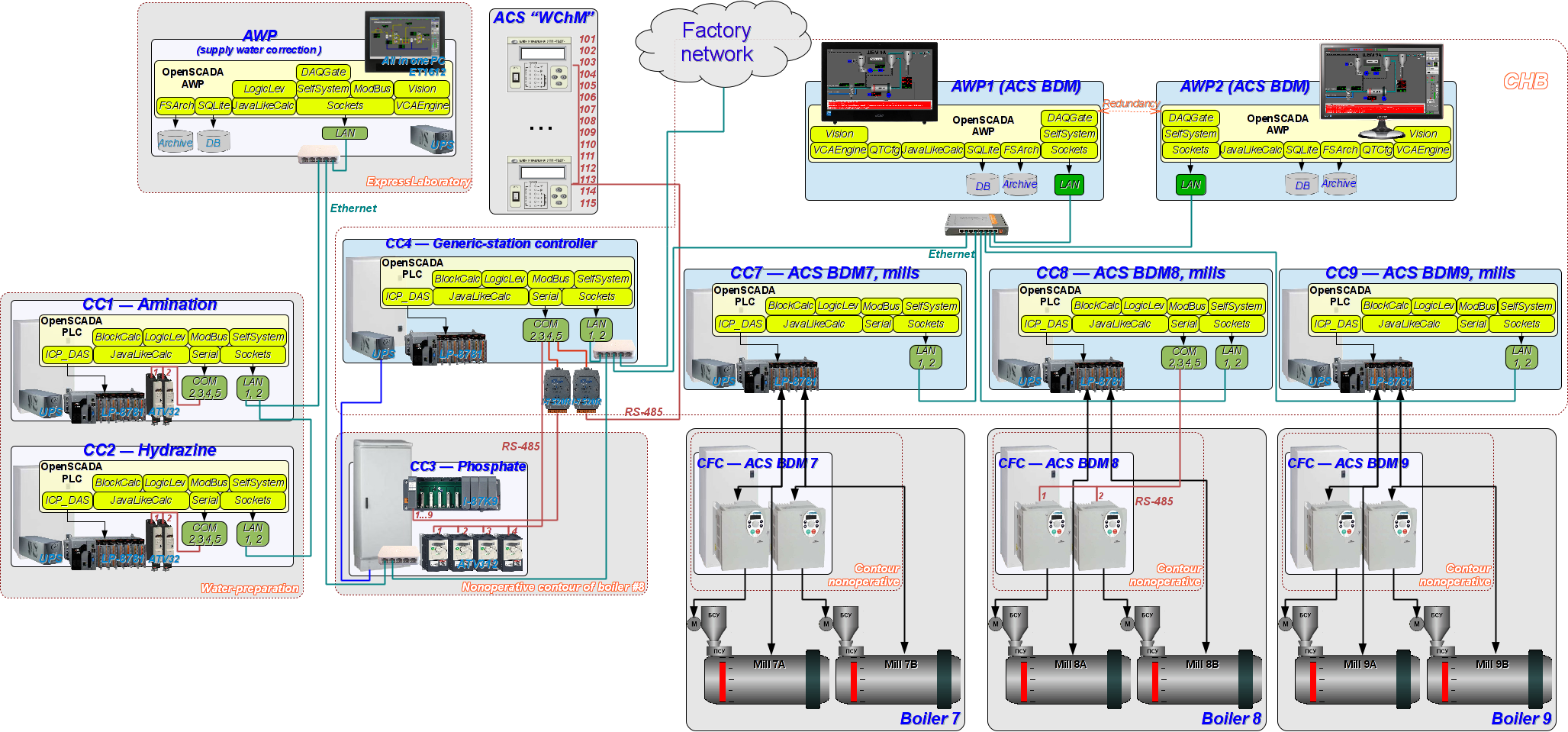
Рис. 3. Structural scheme of the ACS as a part of DIYA Ltd automation solutions and the common network.
In accordance to the structure above the ACS contains the object of automation — mills, controllers of the mills control (CC 7, 8 and 9), frequency converters (CFC 7, 8 and 9), and two automation workplaces (AWP 1 and AWP 2). Each of the controller of ACS BDM independent controls by mills of the concrete boiler. Then the controller CC7 manages by mills of the boiler 7, CC8 — by mills of the boiler 8, and CC9 — of the boiler 9. Link to the frequency converters (FC) performs exclusively by physical signals, for ACS BDM 7 and 9, and also by an interface channel RS-485 by protocol ModBus/RTU, in case of ACS BDM 8.
The technological process data are concentrated and presented on AWPs. Each workplace presents the TP (Technological Process) data of all boilers. With each other workplaces are connected in redundant scheme that prevents data loss at the time of stopping one of the workstations. In order to optimize the load on the controller the real acquisition of the controllers makes only one workplace, while another one is receiving data from the main one. The main workplace is "AWP 1", which performs a direct acquisition of the controllers. In case of failure of the "AWP 1" the controller's acquisition performs "AWP 2", and makes it until the restoration of an "AWP 1". In the process of restoration after failure of the workplace the synchronization of archives depths up to 1 hour is made. Restoration of the archives for the longer time interval is made simultaneously with access to these archives. Addition ACS "Continuous venting" data sown on the AWPs (CC4).
All the nodes of ACS BDM connected to network ACS BDM, into self masc, which physically has an enter to the factory network.
In process of implementing ACS BDM 8 (year 2015) there was been updated PLC ACS BDM 7, 9 in point of the algorithms unification, errors fixing and optimization. Also there was been replaced to new the main AWP 1, represents as a monoblock PC. AWPs' program environment was full updated, and the project of SCADA-system was appended.
2.1. PLC
As a programmable logic controller in the project used PLC LP-8781 of ![]() ICP DAS company of LinPAC family. The industrial controller of this family is the first product built on the x86-compatible processor and it is free from low performance into float-point calculations of the environments based on ARM processors.
ICP DAS company of LinPAC family. The industrial controller of this family is the first product built on the x86-compatible processor and it is free from low performance into float-point calculations of the environments based on ARM processors.
A special feature of the technological process of this project is the availability of specific requirements to the resources and functions of the controller having the small set of parameters. Moreover, the decisive factor is the limited funding. All these requirements are satisfied by a LP-8x81 family of controllers:
- relatively low price;
- possibility, availability and presence of modules of fast data acquisition: I-8017HW (BDM 7 and 9), I-8014 (BDM 8);
- high performance for PLC;
- architectural and programmatic openness of the PLC;
- industrial design and extended temperature range.
PLC (Fig. 4) is structurally made in a modular manner, where the modules are installed in the rack. Rack is combined with a processor module and can have 1, 3 or 7 slots for expansion modules. Expansion modules can be of two types, that is modules in parallel and serial bus. Modules on the parallel bus (I-8x) are fast. Modules on the serial bus (I-87x) are installed on the bus of RS-485 interface and operate at a speed of 115000 bps on the DCON protocol. In addition to modules directly into the rack the controller can be expanded with additional racks with modules on the serial bus (I-87x) through the serial interfaces of the processor.
")
Fig. 4. PLC of LP-8x81 family.
The controller's CPU has next technical characteristics:
| CPU | AMD LX800 processor (32-bit and 500 MHz) |
| System memory | 1 GB RAM |
| Dual Battery Backup SRAM | 512 KB (for 5 years data retain) |
| Flash | 4 GB as IDE Master |
| EEPROM | 16 KB Data Retention: 40 years; 1,000,000 erase/write cycles |
| CF Card | 8 GB (support up to 32 GB) |
| 64-bit Hardware Serial Number | Yes |
| Dual Watchdog Timer | Yes |
| VGA | 640 x 480 ~ 1024 x 768 |
| Ethernet Port | RJ-45 x 2, 10/100 Base-TX Ethernet Controller (Auto-negotiating, auto MDI/MDI-X, LED indicator) |
| USB 1.1 (host) | 2 |
| COM1 | Internal communication with I-87K modules in slots |
| COM2 | RS-232 (RxD, TxD and GND); Non-isolated |
| COM3 | RS-485 D2+,D2-;self-tuner ASIC inside Isolation 3000 VDC |
| COM4 | RS-232/RS-485 (RxD, TxD, CTS, RTS and GND forData- for RS-485); RS-232, Data+ and Data- for RS-485); Non-isolated |
| COM5 | RS-232 (RxD, TxD, CTS, RTS, DSR, DTR, CD, RI and GND); Non-isolated |
| Input Range | +10 VDC ~ +30 VDC |
| Operating Temperature | -25 °C ~ +75 °C |
Overall capacity of the ACS is:
- for ACS BDM 7 and 9: 18(24)AI, 2(4)AO, 10(16)DI, 16(16)DO.
- for ACS BDM 8: 18(28)AI, 9(32)DI, 12(32)DO.
Accordingly there is needs a controller with several extension slots no less to 6, at result there was selected controller LP-8781, which fill by modules is:
| Slot | Module | Notes |
| ACS BDM 7 and 9 | ||
| 1, 2, 3 | LP-8781 | Rack to 10 slots with the processor in slots 1-3 |
| 4 | I-87019RW | 8-channels AI of common purpose (inputs of the mill A). |
| 5 | I-87019RW | 8-channels AI of common purpose (inputs of the mill A). |
| 6 | I-8017HW | 8-channels fast AI (10 kHz), for two channels of vibra-signal. |
| 7 | I-87024W | 4-channels AO for control two frequency drivers of suppliers of mills A and B. |
| 8 | I-8042W | 16 channels DI and DO of common purpose; only input channels are used. |
| 9 | I-87057W | 16 channels DO of common purpose. |
| 10 | Free | |
| ACS BDM 8 | ||
| 1, 2, 3 | LP-8781 | Rack to 10 slots with the processor in slots 1-3 |
| 4 | I-87017ZW | 10-channels AI of common purpose (inputs of the mill A). |
| 5 | I-87017ZW | 10-channels AI of common purpose (inputs of the mill B). |
| 6 | I-8014 | 8-channels fast AI (250 kHz), for two channels of vibra-signal. |
| 7 | I-87040W | 32 channels DI of common purpose. |
| 8 | I-87041W | 32 channels DO of common purpose. |
| 9 | Free | |
| 10 | Free | |
The rapid data acquisition module I-8014, instead I-8017HW, was tested and applied into the ACS BDM.
I-8017HW in general creates high load to the central processor (CP), and prevents to data getting often to 10000 samples for second and demand the hard realtime to the operation system (OS), and also a high resolution timer and it's stability into the PLC. But a data acquisition procedure from the module was optimized into OpenSCADA, and the Fast Fourier Transfer (FFT) algorithm call was adapted to "torn" data stream that is in general improved the coal's level measurement result's quality into the mills for ACS BDM 7 and 9.
I-8014 contains appreciable buffer of measuring it is FIFO and in theory it must allow to get 250000 samples for second (refer to the manufacturer's specification) without significant load of CP. In real it is impossible, for continuous data stream, but a function of reading data from FIFO is long and produces high loading to CP itself. Then maximum frequency of measurement which was been taken it is 100000 samples for second, but that is better then results of the module I-8017HW and there is mostly withdrawn demand to the OS and PLC realtime.
Firmware of the program environment created according to the instruction here.
2.2. AWP
In role of automated work places (AWP) used one from the AWPs of previous project (ACS BDM 7,9) and installed a new AWP based on monoblock PC "Acer Aspire Z1–601" (Fig.5). Such model of AWP was selected but it has low energy consumption at this power of high and enough in overall (the fans lack at all). For go fully moving parts, even more the energy consumption decreasing and as following result it is more reliability to it was installed a solid state drive (SSD) by it's capacity in 60GB, which will enough more then to 20 years, for the like value project, to high quality archives (periodicity in one second).
")
Fig. 5. AWP in base of monoblock PC "Acer Aspire Z1-601".
Automated work places (AWP) of operator were implemented in base of a monoblock PC and an office PC in followed configuration:
| Component | AWP 1 (monoblock) | AWP 2 |
| Processor | Intel Celeron N2830 (2.16 GHz), two core | AMD Athlon 64 X2 5200+ |
| System board | - | ASUS M3N78 |
| Operational memory | DDR3 4 GB | 2 x DDR2-800 1024Mb Hynix PC6400 orig. |
| Solidstate/hard drive | SSD: Goodram C40 60GB 2.5" SATAIII MLC | HDD: WesternDigital WD1600AAJS 160Gb SATA300 |
| Interfaces | RJ-45, 3 x USB 2.0, 1 x USB 3.0, WLAN | - |
| MultyMedia | Stereo dynamics with the technology Dolby Home Theater Audio v4; microphone; Web-camera 1Mp; CardReader MMC/SD/SDHC | - |
| Keyboard | Acer OM-130006A/M | Logitech Deluxe 250 Keyboard Black PS/2 |
| Mouse | Acer OM-130006A/K | Logitech RX300 |
| Display | 18.5" WXGA (1366x768) | 19" Samsung SM 923NW 300cd 1000:1 170/160 5ms RGB (LS19HANKSHED) |
| Power consumption | PS: 65W, Measured (work load): 10W | - |
System unit AWP 2 installed in the cabinet of the operator's table. The operator's table is equipped with monoblock of AWP 1, display of AWP 2 and mouse manipulators. Cabinet with the AWP 2 system unit was closed with doors on the both sides. On the doors the filters are installed, and one of them has fan. Despite of the presence of the fan and because of the large saturation of the room with coal dust the overheating of the system units and failures took place (especially when there were two ones). To solve this problem, it was optimized the air moving in the cabinet, and also lowered the frequency of AWP 2 processors from 2500 to 1600 MHz, and therefore there was replaced one AWP to a fan-less and in generic low consumptive monobloc PC into AWP 1, with implementation of this ACS.
At the AWPs was installed the system software environment of Debian 8 and the SCADA-system OpenSCADA 0.9-Work.
The following activities on the system-wide configuration were done, which were collected to an archive and transferred to the customer together with a disk of ACS "BDM" project:
- The time synchronization was configured of controllers PLC 7, PLC 8, PLC 9 and AWP 2 with AWP 1.
- An account of the operator "op" with the password by default was created.
- An automatic loading of the working interface on behalf of the operator and the launch of the OpenSCADA with the ball mills ACS project was configured.
- TDE desktop environment is configured to eliminate unnecessary functions when working with dialog boxes and excluding the possibility of closure of the operator interface by the mouse.
2.3. UPS
To ensure the uninterruptible power supply of PLC and AWPs there were used the applied uninterruptible power supplies (UPS) PowerCom SKP 1000, for ACS BDM 8, and Mustek PowerMust 1000, for ACS BDM 7,9 (Fig.6).
")
Fig. 6. UPS PowerCom SKP 1000 and Mustek PowerMust 1000.
Used UPSes specification:
| Parameter | PowerCom SKP 1000 | Mustek PowerMust 1000 |
| Architecture type | Line-Interactive | |
| Outlets number | 6 | 3 |
| Output power | 1000 VA / 600 W | |
| Input voltage range at working from network | 220 V, 230 V, 240 V, ±25%, 1-phase | 162 - 290 V |
| Working time at full load | 30 minutes (really it is 48 minutes at the load in 100W) | 15-20 minutes |
| Pulse protection, J | 320 J 2ms | - |
| Used battery type | 2 x 7A*hours-12V, "hot replacing", Lead-Acid, hermetic, no service needs, with increased working time (really provides the capacity only 104W*hours, instead the typical 170W*hours) | 2 x 7A*hours-12V, "hot replacing", Lead-Acid, hermetic, no service needs |
| Battery charging time, hours | 4 (up to 90% from the full capacity) | 6 (up to 90% of the capacity) |
| Dimensions | 140 х 380 х 210 | |
| Weight | 13.9 kg | |
| Output curve, from battery | Almost true sine | Modified sine, pulses in fact |
For the UPS of ACS BDM 7,9 connection was used a RS-232 (COM2) interface of the controller, in which assistance the connection NUT performs with the configuration part into file "/etc/nut/ups.conf":
For the UPS of ACS BDM 8 connection was used an USB interface of the controller, in which assistance the connection NUT performs with the configuration part into file "/etc/nut/ups.conf":
The device's exclusively file "/dev/powercom" creation and the NUT driver reloading at some reconnections perform by the row into UDEV file "/etc/udev/rules.d/90-nut-usbups.rules":
2.4. FC
To free control for productivity of SRC there was used the frequency converter (FC) of firm ![]() ShniderElectric ATV312HU40N4 (Fig.7) which has power 4kW and supplied from an average current network of 380V. FC was connected to motor of power 3 kW, which same performs the SRC to motion.
ShniderElectric ATV312HU40N4 (Fig.7) which has power 4kW and supplied from an average current network of 380V. FC was connected to motor of power 3 kW, which same performs the SRC to motion.
")
Fig. 7. FC ATV312HU40N4.
Common specification of the rotation system by the frequency converter is follow:
| Motor | |
| Type | Asynchronous 3-phases |
| AC supply frequency, Hz | 50 |
| Voltage, V | 380 |
| Nominal current, A | 4.7 |
| Rotation frequency, rpm | 1480 |
| Power, kW | 2 |
| FC: ATV312HU40N4 | |
| Range of product | Altivar 312 |
| Product destination | Asynchronous motors |
| Assembly style | With heat sink |
| Motor power, kW | 4 |
| Motor power, hp | 5 |
| [Us] rated supply voltage, V | 380...500 (- 5...5 %) |
| Supply frequency, Hz | 50...60 (- 5...5 %) |
| Network number of phases | 3 |
| Line current, A | 10.6 for 500V; 13.9 for 380V, 1kVA |
| EMC filter | integrated |
| Apparent power, kVA | 9.2 |
| Maximum transient current for 60s, А | 14.3 |
| Power dissipation, W | 150 |
| Speed range, Hz | 1...50 |
| Asynchronous motor control profile | Factory set : constant torque Sensorless flux vector control with PWM type motor control signal |
| Electrical connection | Al1, Al2, Al3, AOV, AOC, R1A, R1B, R1C, R2A, R2B, LI1...LI6 terminal 2.5 mm² AWG 14 L1, L2, L3, U, V, W, PA, PB, PA/+, PC/- terminal 2.5mm² AWG 14 |
| Supply | Internal supply for logic inputs at 19...30 V <= 100 A for overload and short-circuit protection Internal supply for reference potentiometer (2.2 to 10 kOhm) at 10...10.8 V <= 10 A for overload and short-circuit protection |
| Communication port protocol | ModBus |
| IP degree of protection | IP20 on upper part without cover plate IP21 on connection terminals IP31 on upper part IP41 on upper part |
Control the FC performs from the PLC by physical signals, for ACS BDM 7,9, by interface RS-485 and protocol ModBus/RTU, for ACS BDM 8. The parameters of connection with the FC into module of transport interface "Serial" of OpenSCADA are following values:
- Speed: 19200,
- Configuration: 8E1,
- Timeouts: 100:5,
- Limit to ModBus registers per package: 30.
For tune-up, work out, detection and notification about errors there was performed tries to reproduce following errors:
- OLF — Motor overloading. Forming at the parameter SUP-/tHr (thermal motor state) achieving to 118%. The error quittance is possible after SUP-/tHr decreasing down to 53%. SUP-/tHr depends from SUP-/ItH (thermal motor state).
- OPF — Motor phase lost. Forming at disabling/loss one motor phase, FC stops the motor (lag in 1s.). The motor is possible to start after return the phase and the error clean up.
- SLF — Connection by ModBus error. Forming after any activity lack with the controller at the remote control.
- OHF — FC overheating. Forming in case of achieving by parameter SUP-/tHd (FC thermal state) to 118%. Unable to reproduce.
- PHF — One supply phase line loss. Forming in case disabling/loss one supplying pase. Unable to reproduce.
3. Algorithms
The control algorithms of the ball mills are quite complex, due to the following factors:
- The use of indirect mechanisms to obtain the values of the level of coal in the mill.
- Accounting of different ways of control the loading of the mill, from the direct regulation of temperature of dusty mixture at the outlet from the mill to control the loading on the calculation of the coal level inside the mill.
Using the algorithms the programs of the controller designed for loading control of ball mills were created. In the algorithms and programs the analog and digital signals coming from the inputs (to output) of analog and discrete modules of the controller, the signals, generated by the workstation, and the intermediate signals, generated on their basis, were used.
Programs are implemented in user programming languages of the OpenSCADA system. Block schemes are implemented in the environment of the DAQ.BlockCalc module, but the realization of the blocks itself and templates of parameters — on the JavaLikeCalc language of the DAQ.JavaLikeCalc module of the OpenSCADA system.
3.1. Pre-processing
For pre-processing of analog signals after ADC of the analog input module of the controller the template of parameters was created with the following functions:
- detecting of uncertainty (the break, out of range of acceptable values);
- corrections using the calibration coefficients, or real hardware border;
- filtration;
- bring to the engineering (technological) units;
- formation of the alarm bits for violations of borders;
- simulation of analog input as with the built-in function, and with the external input, which can be used to connect the signal model.
Based on this template the additional templates were created:
- template of the parameter of manual input, with the additional function of input the value;
- template of the universal PID parameter with the reflection of its own attributes of the analog and pulsed regulator.
For the grouping and processing the discrete signals the template of a discrete parameter was created, which allows you to:
- combine two digital inputs and three digital outputs in the configuration of pumps and valves.
3.2. General algorithms
Common algorithms are summarized in two block schemes for each mill. The first block scheme contains the contours of analog regulators and work with a period of 500ms. The second block scheme contains the contours of pulsed regulators and operates with a period of 100 msс.
4. User interface
Information about the technological process represents on video-cadres forming by the program of displaying on a display's screen as part of each AWP. The displaying information has a defined output area into the video-cadre and depends from it's destination. On figure 8 by digits is pointed the output areas of the video-cadre:
2. panel of selection of displaying type, navigation by the video-cadres and local quittance;
3. panel of control;
4. workplace of the displaying;
5. active violation tables;
6. panel of states with instruments.
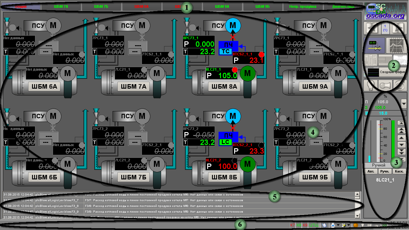
Fig. 8. Video-cadre structure
The controlling object divides in functions and technological to blocks which call as the signal objects. To each of the signal object assigns some grouped video-cadres set. The signal object represents set of screen's buttons for the objects and it's linked video-cadres' groups selection.
The signal object includes following buttons:
- "Common" — group of the common control to main technological equipment.
- "BDM 7A" — group of video-cadres to control BDM 7A.
- "BDM 7B" — group of video-cadres to control BDM 7B.
- "BDM 8A" — group of video-cadres to control BDM 8A.
- "BDM 8B" — group of video-cadres to control BDM 8B.
- "BDM 9A" — group of video-cadres to control BDM 9A.
- "BDM 9B" — group of video-cadres to control BDM 9B.
- "Uninter. Flow" — group of video-cadres for control to the uninterrupted flow of the boilers.
- "Diagnostic" — group of video-cadres of the automation equipment diagnostic.
To each of signal object can be linked next types of video-cadres:
- mnemonics;
- groups of graphic;
- groups of overview graphics;
- groups of parameter's contours;
- documents.
Singly to the whole interface can be linked summary graphics.
4.1. Mnemonics
The mnemonics window calls by pressing to proper button of the representing type and pointed to:
- graphical (mnemonically) representing of a frame of the control object;
- representing of current state of parameter into a graphical view;
- representing current state of parameter into a text view;
- call to a window of the parameter to the control panel.
ACS in general represents by mnemonics, one to each signal object: "Generic" (Fig. 10), "BDM 7A", "BDM 7B", "BDM 8A" (Fig. 9), "BDM 8B", "BDM 9A", "BDM 9B", "Uninter. Flow" (Fig. 11), "Diagnostic" (Fig. 12). Also for the project there were created two private dialogs of the level calibration (Fig. 13) and configuration of a algorithm of optimization (Fig.14).
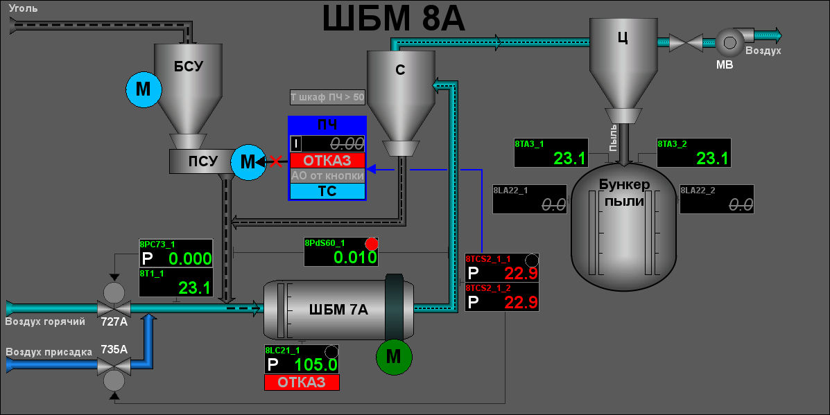
Fig. 9. Mnemonic "Mill 8A".
Fig. 10. Mnemonic "Generic".
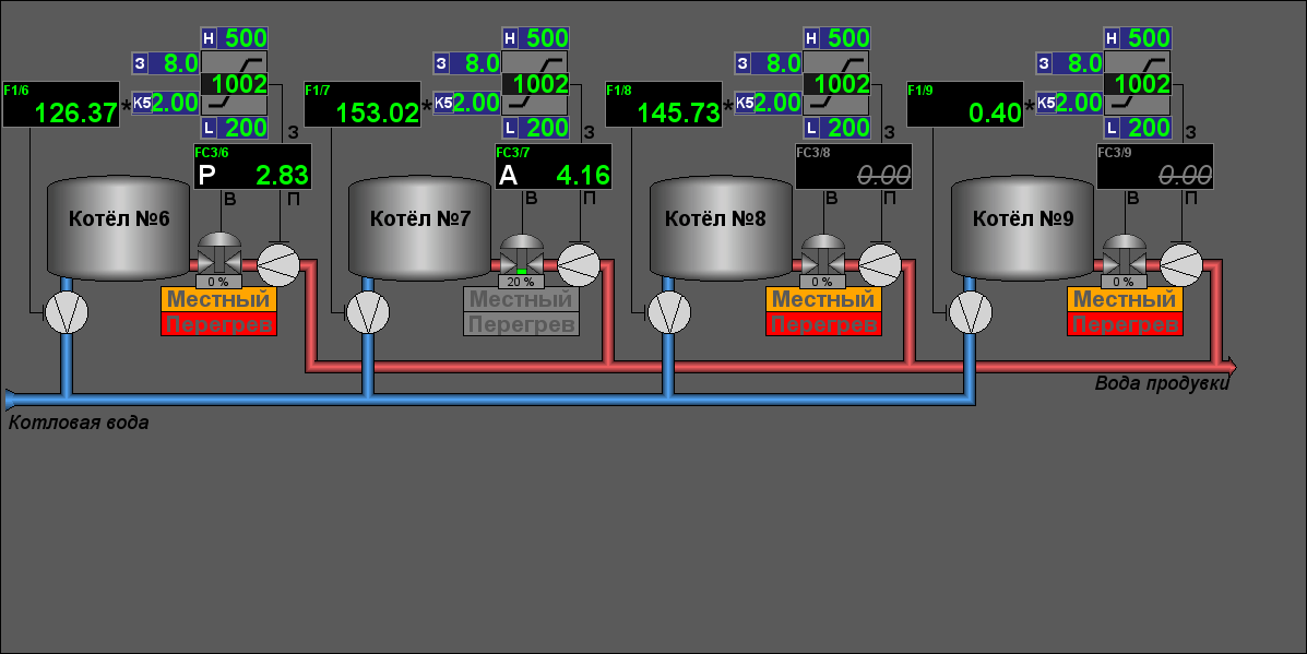
Fig. 11. Mnemonic "Uninter. Flow".
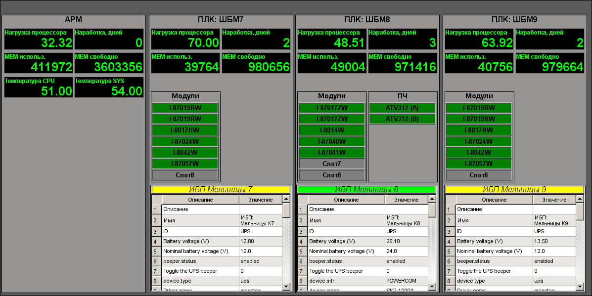
Fig. 12. Mnemonic "Diagnostic".
")
Fig. 13. Dialog "Level calibration".
")
Fig. 14. Dialog "Configuration of a algorithm of optimization".
4.2. Group of graphics of parameter's values
The window of group of graphics calls by pressing to proper button of the representing type and appointed for view of values up to ten parameters into graphical view for pointed time.
There provided twenty groups of graphics of technological parameters in next configuration per the signal objects:
- BDM 7A: "Mill 7A", "Mill 7A: FC, SRC"
- BDM 7B: "Mill 7B", "Mill 7B: FC, SRC"
- BDM 8A: "Mill 8A" (Fig.15), "Mill 8A: FC, SRC" (Fig.16), "Dust bunker of the boiler #8" (Fig.17)
- BDM 8B: "Mill 8B", "Mill 8B: FC, SRC", "Dust bunker of the boiler #8"
- BDM 8A: "Mill 8A", "Mill 8A: FC, SRC"
- BDM 8B: "Mill 8B", "Mill 8B: FC, SRC"
- Uninter. Flow: "Flows" (Fig.18), "Flow valves" (Fig.19)
- Diagnostic: "AWP" (Fig.20), "PLC: Mills 7", "PLC: Molls 8" (Fig.21), "PLC: Mills 9"
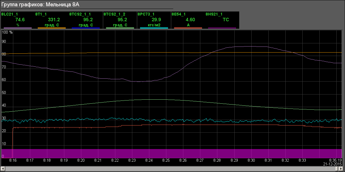
Fig. 15. Group of graphics "Mill 8A".
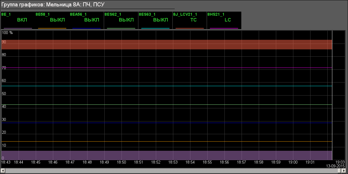
Fig. 16. Group graphics "Mill 8A: FC, SRC".
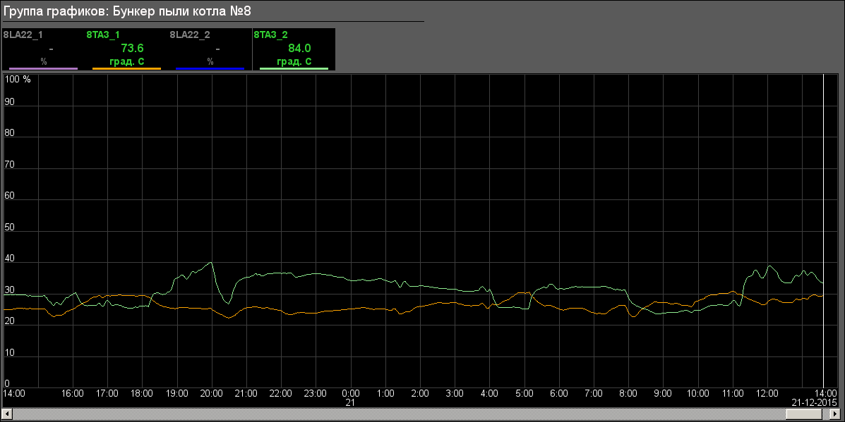
Fig. 17. Group graphics "Dust bunker of the boiler #8".
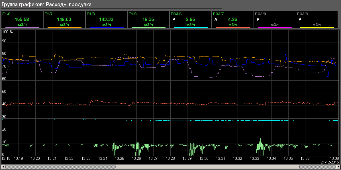
Fig. 18. Group graphics "Flows".
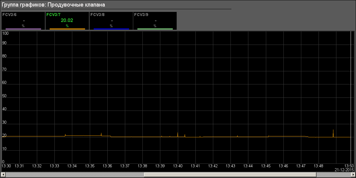
Fig. 19. Group graphics "Flow valves".
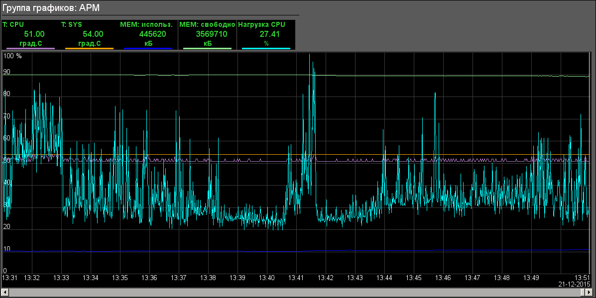
Fig. 20. Group graphics "Diagnostic of AWP".
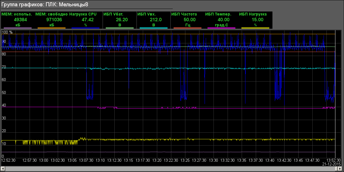
Fig. 21. Group graphics "Diagnostic of PLC: Mills 8".
4.3. Contours of parameters
The video-cadre "Group of contours" calls by pressing to proper button of the representing type and appointed for view several windows of control (regulators-contours, deblock keys, motors and other) into single video-cadre to provide comfort into the parameters observing and interruption.
There provided only single group of contours to each mill, as on the figure 22 for mill 8A.
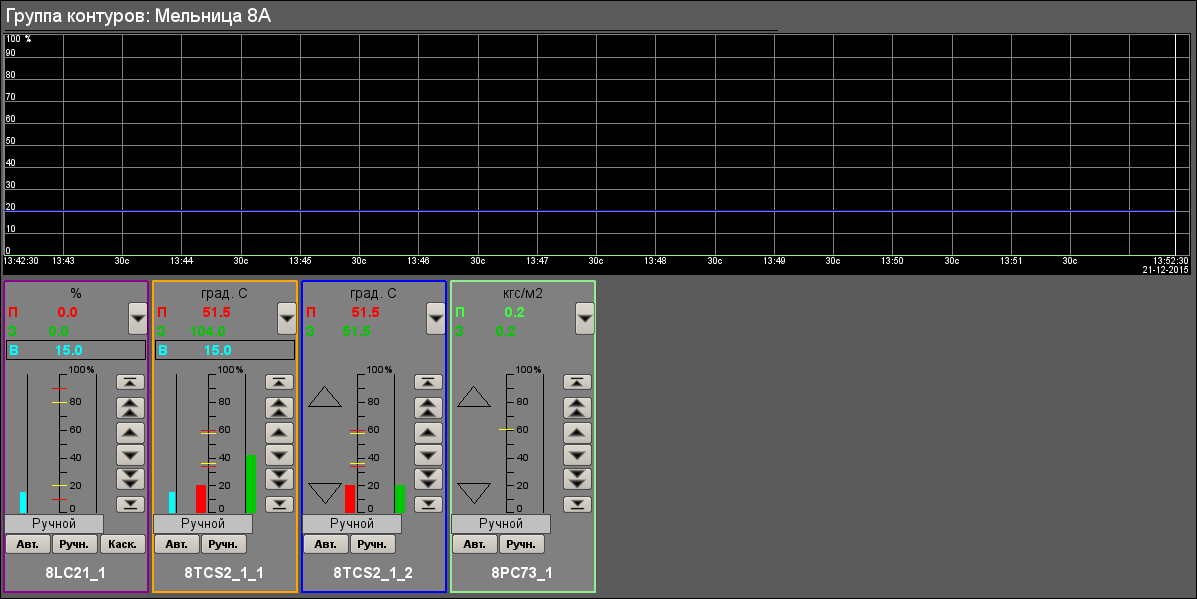
Fig. 22. Group of contours "Mill 8A".
4.4. Overview cadre
The window of the overview cadre calls by pressing to proper button of the representing type and appointed for:
- parameter's value overview in graphical view for current time;
- parameter's current state overview into text;
- parameter selection for control (regulation) on a proper panel.
There provided only single overview cadre to each mill, that as on figure 23 for mill 8A.
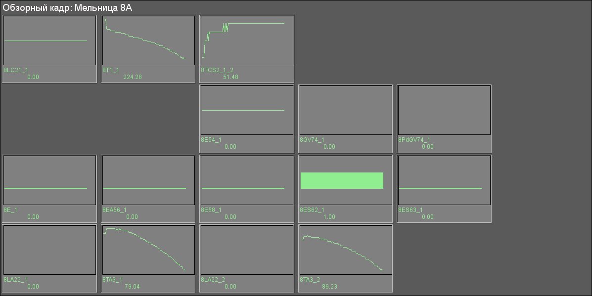
Fig. 23. Overview cadre "Mill 8A".
4.5. Summary graphics
Window of the cadre of result graphics calls by pressing to proper button of the representing type and appointed for concentrated, in general, view of parameters' trends in graphics (up to 80). The group of result graphics does not linked to concrete the signal object but has been a part of the interface in whole.
There provided only single cadre of result graphics to the interface in whole (Fig. 24).
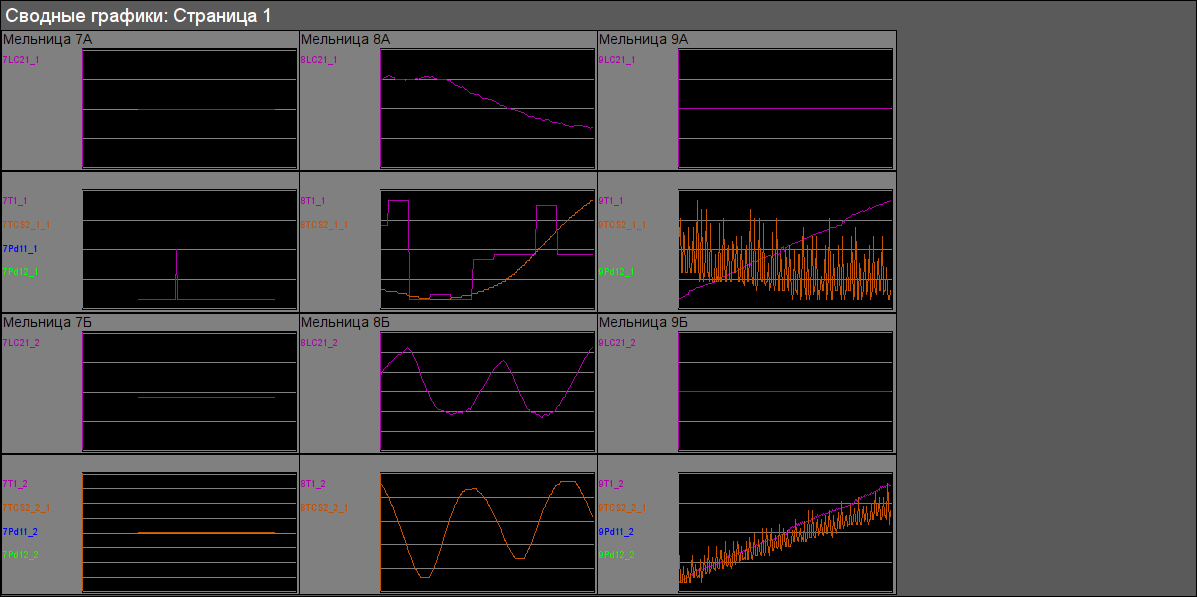
Fig. 24. Cadre of the result graphics "Page 1".
4.6. Documents
The documents window calls by pressing to proper button of the representing type and contains a document from a list of allowed.
4.6.1. Protocol of interruption
The protocol of interruption (Fig. 25) provides for overview of operator doings which performed from same AWP (changing of deblock keys stats, modes, configuration coefficients of regulators and other).
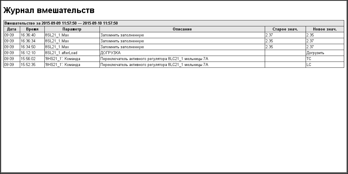
Fig. 25. Protocol of interruption.
4.6.2. Protocol of violations
The protocol of violations (Fig. 26) provides for overview the violations in selected signal object (violation of order boards, inauthenticity, diagnostic of parameter and other).
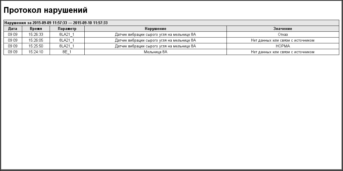
Fig. 26. Protocol of violations.
4.6.3. Report of machinist
The report of machinist (Fig. 27) provides to form a report of measured parameters for change with the interval in 1 hour.
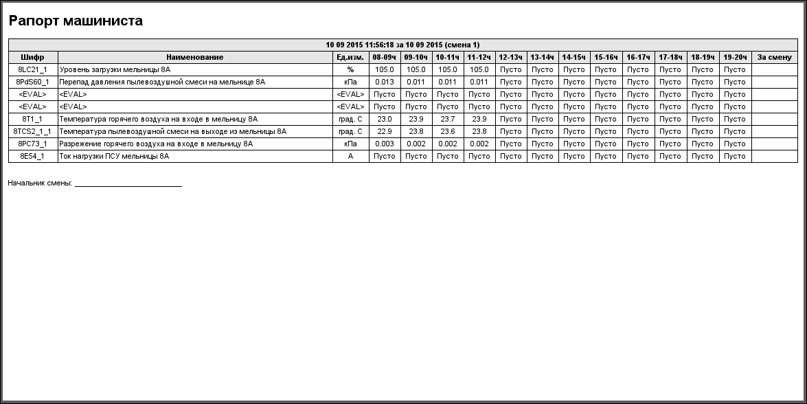
Fig. 27. Report of machinist.
5. Results
As a result of this work the industrial control system was obtained, the result of which is the savings of coal and electricity up 30%, due to the uniformity of the load of the mills and decreasing of working continuance.
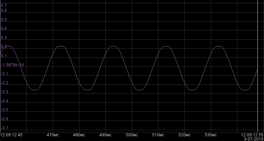
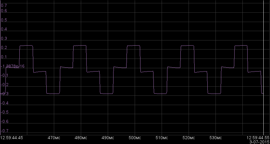
In Figures 28 and 29 the diagrams of mill control on load are shown, and in the Figures 30 and 31 on the temperature of dust-air mixture after the mill.
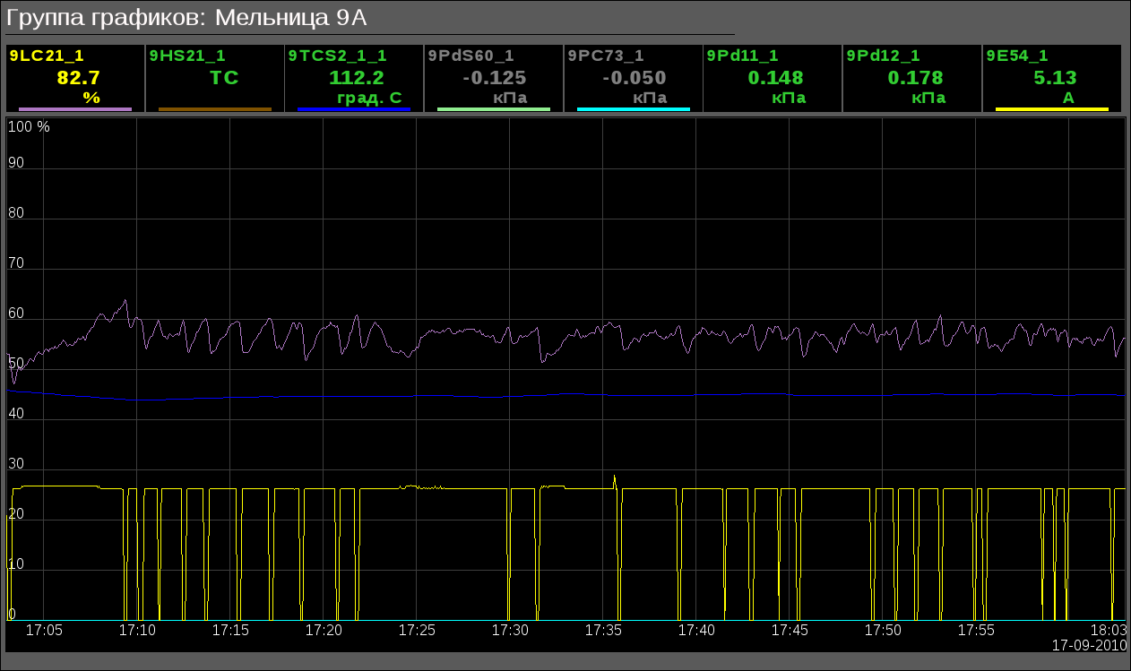
Fig. 28. The control of the mill on load.
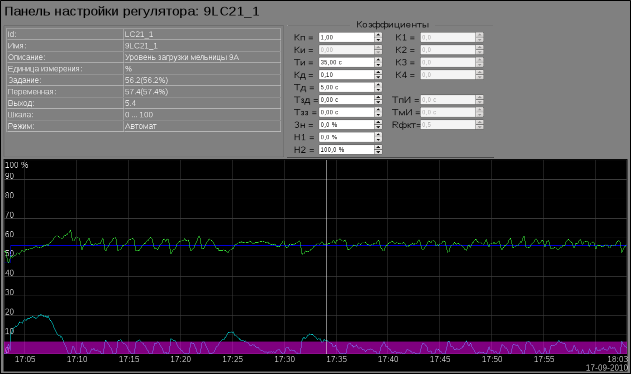
Fig. 29. The control of the mill on load in the regulator's control panel.
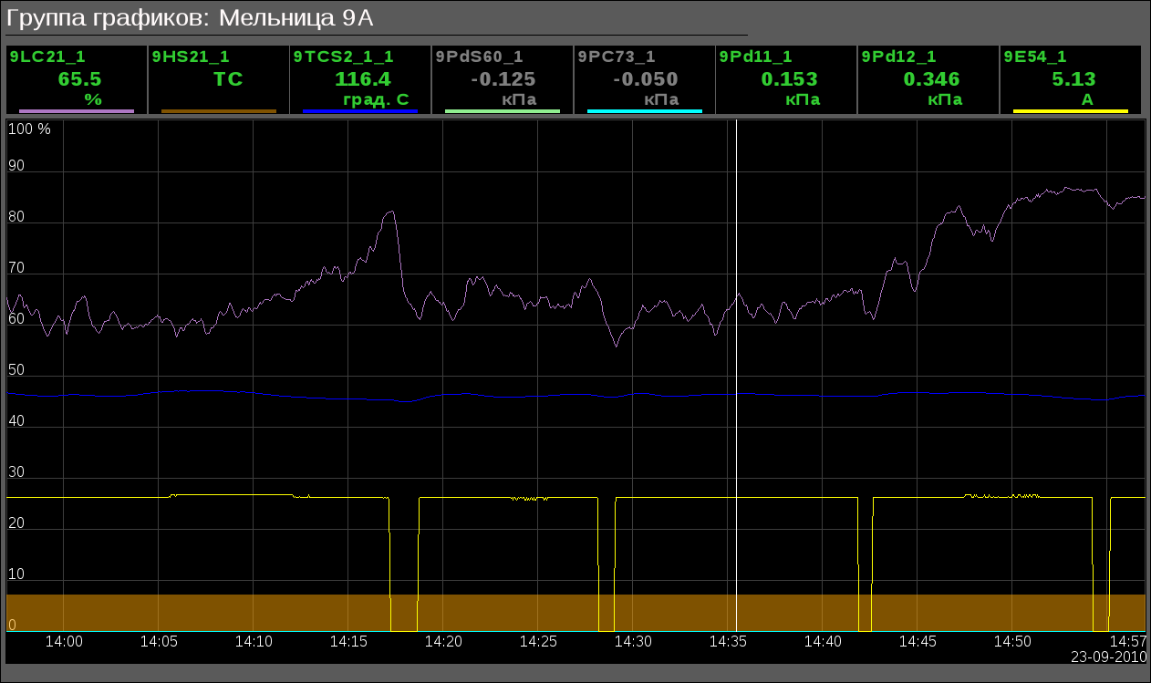
Fig. 30. The control of the mill on the temperature.
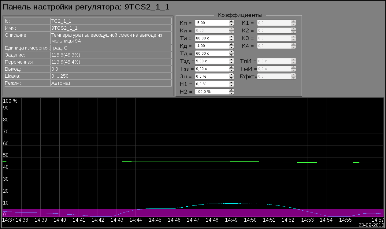
Fig. 31. The control of the mill on the temperature in the regulator's control panel.
6. Economical effect
As a result of the work a significant economic effect is received, the calculation and the nature of which is held in the table below. The effect is calculated by the customer based on actual statistical data. In the period from 06/21/2010 to 06/30/2010 the work of mills was made in the manual mode and without ACS. In the period from 08/21/2010 to 08/30/2010 the ACS BDM worked in the automatic mode.
| № | Name of a parameter | Unit | 21/06/2010 - 30/06/2010 | 21/08/2010 - 30/08/2010 |
| 1. | Consumption of coal | tons | 3235 | 2880 |
| 2. | Electricity consumption for grinding | kWh | 132780 | 98066 |
| 3. | Specific power consumption for grinding | kWh/ton | 41.04 | 34.05 |
| 4. | Milling dispersity | % | 8.70 | 7.60 |
| 5. | Combustible in the ash | % | 31.90 | 30.60 |
| 6. | Boiler efficiency, gross | % | 83.40 | 83.76 |
| 7. | Reducing power consumption for grinding | kWh | - | 20131 |
| 8. | Fuel Savings | tons | - | 10.40 |
The act of ACS BDM pilot tests by the customer, describing the economical effect can be downloaded ![]() here.
here.
7. Links