4.2 Formalization
Lets conceptually describe the VCA model using the UML with use case diagram.
Any VCA can operate in two modes - the development and execution. As an actor, in the first case, acts the engineer of the top-level of ACS-TP setting, in the other - the operator.
In development mode lets select the following options of using the VCA:
- Operations over the project:
- open/save an existing visualization project from/to the DB;
- creation/delete of the visualization project;
- work with an open project:
- add/remove the frame into the visualization project;
- linkage the frame of the project with the dynamics (dynamization of the characteristics of the frame), creating the visual interface page or the template for the overall dynamics for the pages based on this frame;
- creation/delete of the visualization interface page based on the frame of the project;
- linkage the page control interface pages with the dynamics.
- opening/closing/connection to the execution session of the project.
- Operations on the frame (widget):
- open/save the widget/frame in the library of the database;
- create/delete of the widget/frame;
- work with an open frame:
- addition/remove the embedded widget on the working frame;
- selection of widgets on the working frame;
- change the properties of the selected widgets by means of the widgets' supervisor;
- grouping/ungrouping of the selected widgets;
- moving the selected widgets by mouse and/or keyboard;
- visual change of the size and other geometric parameters of the widget;
- appointment of the slots of dynamics linkage (parameters) of the widgets or the of the frame as a whole, as well as direct dynamics linkage for the final visualization of widgets (frames);
- formation of the procedure of links description and other logic of the widget, on he language of the user programming provided by the OpenDCADA system;
- associative installation of simple and group logical connections by the graphical and configuration way.
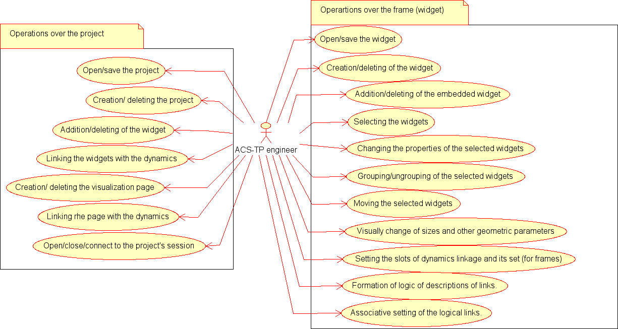
Use case diagram for operation of the VCA in development mode is shown in Fig. 4.2.1.

Fig.4.2.1 Use case diagram of the VCA in development mode.
Using variants in the execution mode:
- tracking of the TP for instantaneous values, diagrams, etc.
- control of technical or other processes (TP) through the final visualization interface;
- navigation through the frames and pages of visualization interface;
- hot swap of dynamised properties of the frames and pages;
- formation and print of the reporting documents, instruments and displays of the visualization interface;
- change of the user.
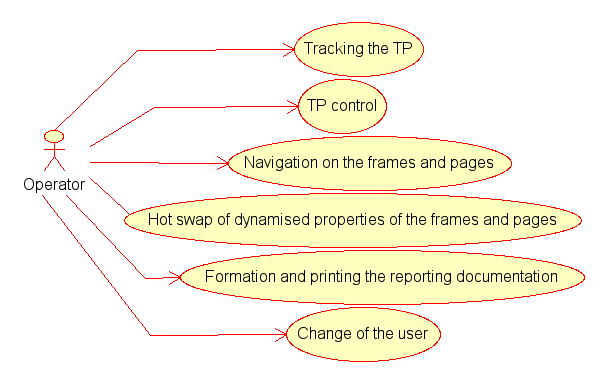
Using diagram of the VCA in the execution mode is shown in Fig.4.2.2.

Fig.4.2.2 Using diagram of the VCA in the execution mode.
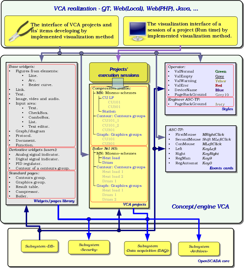
Based on the requirements and general considerations the VCA structure can be represented as it shown on the Fig.4.2.3.

Fig.4.2.3 Generalized structure of the VCA.
It should be noted that this approach allows to implement the support of three levels of complexity of the development process of the control interfaces. As a consequence, an ACS-TP engineer can use (to start) the level at which he has enough skill with the ability to improve it further, actually eliminating the rejection of the system because of the over-complexity at the early stage of learning and saving at the same time the considerable flexibility and power of the system. Lets enumerate these levels:
- VC(visualization and control) interface formation with the help of library of template frames, by placing the frame's templates into the project and their dynamisation.
- In addition to the first level the formation of its own frames on the basis of libraries of derivatives and basic widgets is done. It is possible as the direct appointment of the dynamics in the widget, and the subsequent its appointment in the project.
- In addition to the second level the independent formation of derivatives of widgets, the new template frames, and frames with the use of the mechanism of description of logic of interaction and event processing in the language of user programming of OpenSCADA system.