Lets conceptually describe the VCA model using the UML with use case diagram.
As an actor, in the development mode, acts the engineer of the top-level of "ACS TP" setting, in the execution mode — the operator.
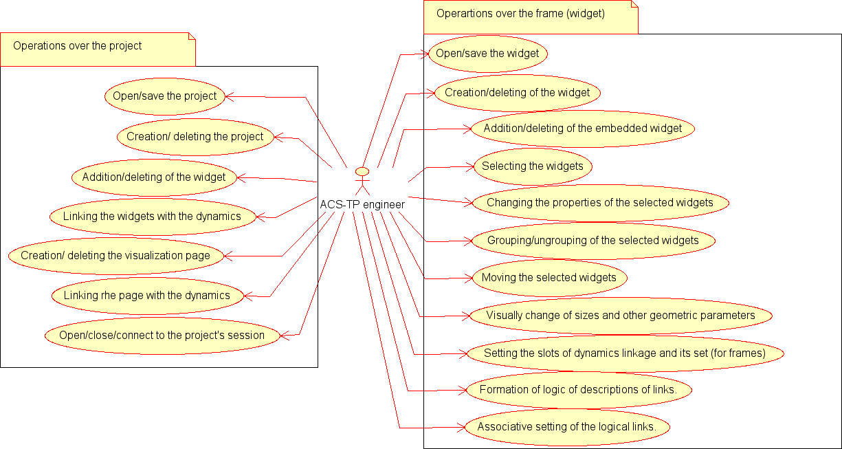
In development mode lets select the following options of using the VCA:
- Operations over the project:
- open/save an existing visualization project from/to the DB;
- create/delete of the visualization project;
- work with an open project:
- add/remove the frame into the visualization project;
- linkage the frame of the project with the dynamics (dynamization of the characteristics of the frame), creating the visual interface page or the template for the overall dynamics for the pages based on this frame;
- create/delete of the visualization interface page based on the frame of the project;
- linkage the page control interface pages with the dynamics.
- open/close/connect to the execution session of the project.
- Operations on the frame (widget):
- open/save the widget/frame in the library of the database;
- create/delete of the widget/frame;
- work with an open frame:
- add/remove the embedded widget on the working frame;
- select of widgets on the working frame;
- change the properties of the selected widgets by means of the widgets' supervisor;
- group/ungroup of the selected widgets;
- move the selected widgets by mouse and/or keyboard;
- visual change of the size and other geometric parameters of the widget;
- appoint of the slots of dynamics linkage (parameters) of the widgets or the of the frame as a whole, as well as direct dynamics linkage for the final visualization of widgets (frames);
- formate of the procedure of links description and other logic of the widget, on he language of the user programming provided by the OpenDCADA system;
- associative installation of simple and group logical connections by the graphical and configuration way.
Use case diagram for operation of the VCA in development mode is shown in Fig. 4.2.1.

Fig.4.2.1 Use case diagram of the VCA in development mode.
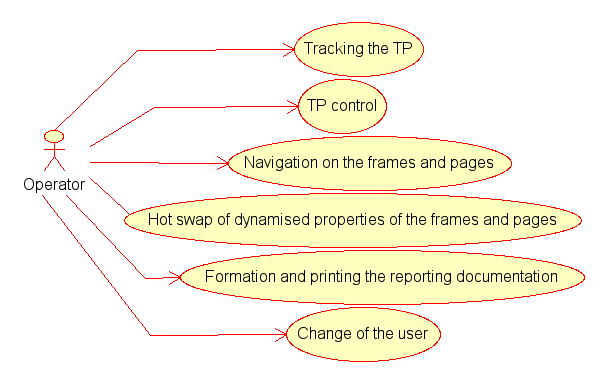
Using variants in the execution mode:
- track of the TP for instantaneous values, diagrams, etc.
- control of technical or other processes (TP) through the final visualization interface;
- navigate through the frames and pages of visualization interface;
- hot swap of dynamized properties of the frames and pages;
- formate and print of the reporting documents, instruments and displays of the visualization interface;
- change of the user.
Using diagram of the VCA in the execution mode is shown in Fig.4.2.2.

Fig.4.2.2 Using diagram of the VCA in the execution mode.
Any VCA can operate in two modes — the development and running. In the development mode the VCA interface and its components are formed, the mechanisms of interaction are identified. While the running it is carried out the formation of VCA interface based on the developed VCA with the final user interaction is made.
VCA interface is formed of the frames, each of which, in its turn, formed from elements of the primitives, or user interface elements. In doing so, the user interface elements are also formed from the primitives or other user elements. That gives us a hierarchy and reuse of already developed components.
Frames and user elements are placed in the libraries of widgets. The projects of the interfaces of the final visualization of the VCA are formed from these libraries' elements. Based on these projects the visualization sessions are formed.
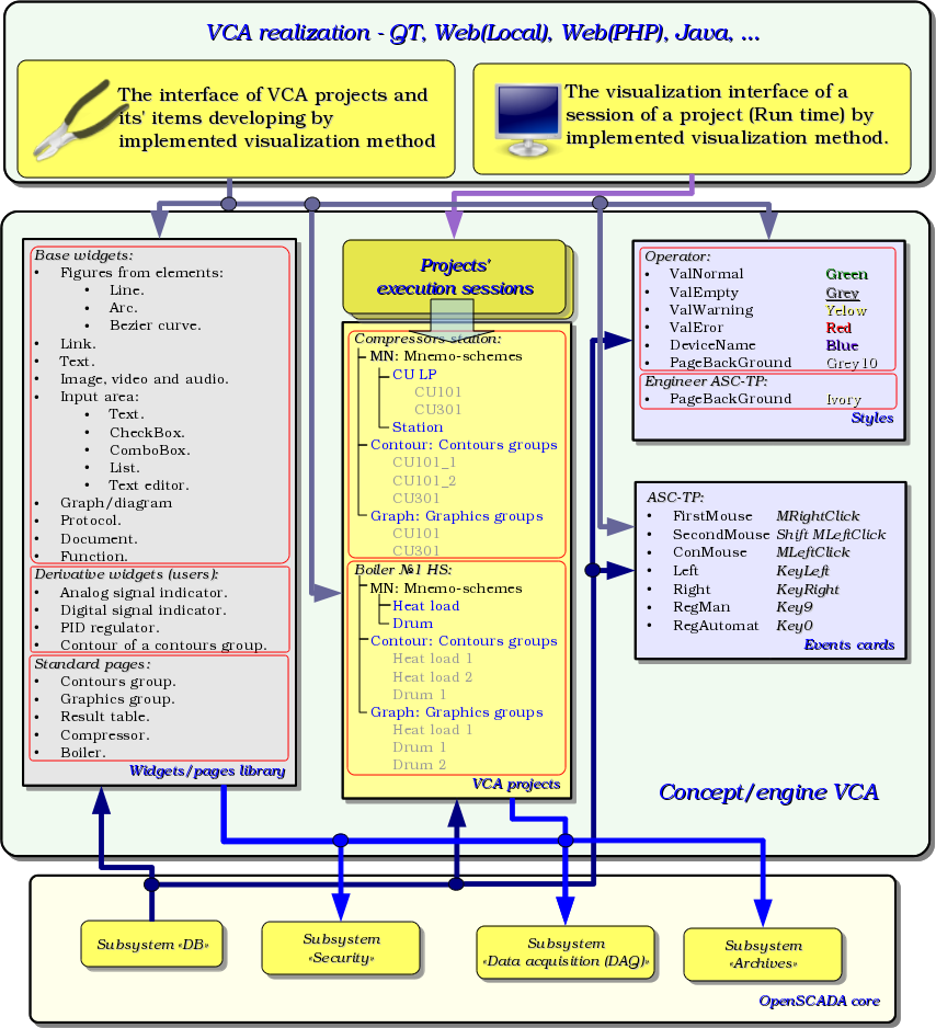
The structure of VCA is shown in Fig. 3.

Fig.3 Generalized structure of the VCA.
This architecture of the VCA allows the support of three levels of complexity of the developing process of the management interface:
- Forming of the VC interface (visualization and control) using the library of template frames by placing the templates of the frames in the project and by the assignment of the dynamics.
- In addition to the first level the own creation of frames based on the library of derivatives and basic widgets is to be done. Perhaps as a direct appointment of the dynamics in the widget, and the subsequent appointment of it in the project.
- In addition to the second level is performed the independently forming of derivatives widgets, new template frames and also the frames with the use of mechanism of describing the logic of interaction and handling of events in one of the languages of a user programming of OpenSCADA system.