ACS of Phosphating, Amination and Hydrazine of boiler BKZ 160–100 PT
| Begin: 11(October) 2013 Finish: 12(December) 2014 + 12(December) 2015 (Continuous blowing) Location: Kramatorsk city, CHP Customer: Limited liability company (Ltd) "Kramatorskteploenergo", Participants: Roman Savochenko, Description: Automation Control System (ACS) of Phosphating, Amination, Hydrazine, Continuous blowing of the boiler's water of boilers BKZ 160–100 PT №6,7,8,9 | 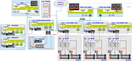 |
Object of automation
In exploitation of Kramatorskteploenergo Ltd is a Central Heat Energy (CHM) in contains of five working boilers BKZ 160–100 PT (5, 6, 7, 8 and 9). The boilers produce steam with pressure 100 kgf/cm2 and nominal productivity up to 160 ton/hour. Produced steam transferred to turbines and heat carrier of Kramatorsk city. As fuel of the boilers use the coal dust and the natural gas, mostly for ignition and light. The primary coal is non-gas (anthracite) coals which is less explosive and allow to milling on temperatures up to 150°С.
For supply of the boilers there uses addition and circulation water. The supply water needs for preparation previously for prevent scum formation and corrosion of the common and additive equipment. Same for correcting of the supply water applies of "Amination", "Hydrazine" and "Phosphating" (for boiler's water).
The corrosion decreasing performs by creation the reductive environment into the condensing tract and deep binding of oxygen and nitrite after deaerator through input Recovery, by regulation of рН value of the environment through input Ammonia. Higher grade of the binding of nitrite and residual oxygen can be doing by hydrazine-hydrate (in this case), hydrazine-sulphate, sodium-sulfate.
For prevent the scum formation the boiler's water processes by phosphates. Phosphating is effective way of preventing only to calcium scum formation. As part of the desalting process it is also continuous blowing of the boiler that is continuous flow of the salting water from the boiler's drum bottom. The continuous blowing also included to the ACS "Phosphating".
ACS
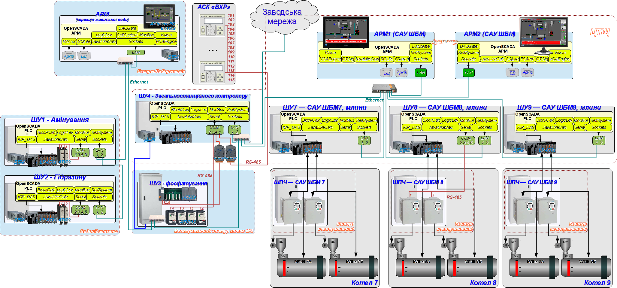
Structural scheme of the ACS shown on Figure 1, it is contains four cabinets of controllers and Automation Work Place (AWP) of operator.
ACS "Amination" and "Hydrazine" located into a single placement "Water-preparation", but them are implemented into different cabinets CC1 and CC2, accordingly. Into each of the cabinets placed an individual controller, and the controller of ACS "Hydrazine" connected to local network through second interface of the controller of ACS "Amination", where both of the interfaces connected to a "Bridge". Main aim of the ACS "Amination" and "Hydrazine" is dosing transfer of ammonia and hydrazine-hydrate to the supply water, which performs by pumps connected through Frequency Converters (FC). Control by the FC performs from the PLC by the link interface RS-485 and the protocol ModBus/RTU.
ACS "Phosphating" divided to two parts. First part is presented by cabinet CC4 (placement of Central Heat Board) and into it installed PLC, and second part is presented by cabinet CC3 (placement of nonoperative contour of boiler #8) with a tray of Object Adjustment Devices (OAD) and frequency converters of pumps of transferring phosphates to boilers #6,7,8,9. Common signals of ACS connected to the OAD tray which self connected to the PLC by the interface RS-485 and the protocol DCON. Control by the FC of transferring phosphates performs from PLC by the link interface RS-485 and the protocol ModBus/RTU. Connecting the PLC to the local network performs by a switch into the cabinet CC3, moreover the two pares of RS-485 and other two of Ethernet routed between the cabinets CC3 and CC4 by single cable of twist pairs of category 5 by length about 100m.
PLC CC4 (placement of Central Heat Board) besides the functions of the ACS "Phosphating" includes also functions of ACS "Continuous blowing" and ACS "Water Chemical Mode (WChM)", and why had it's naming as "Generic-station".
ACS "Continuous blowing", implemented into the generic-station controller, represented by valves of flow rate of continuous blowing with a pulse control. ACS signals entered direct to the PLC modules. Due to need of controlling the ACS by operator of the boilers it's interface entered to ACS BDM, and the Generic-station PLC enabled to network of ACS "BDM".
ACS "WchM" implemented base on devices of analysis the chemical water mode (UPP) from a previous system, which AWP (implemented on the closed technologies) in time was unworkable. That all this devices UPP (15 items), into the network RS-485 by protocol ModBus/RTU, were connected to the Generic-station PLC. Some parameters of the ACS used into ACS "Amination", "Hydrazine", "Phosphating" and "Continuous blowing" for control to transporting/dosing by the analysis. In generic each of the UPP allow to measure following parameters: "Temperature of the sample", "Value of pH", "Value of cNa", "Value of dissolved O2", "Electrolytic conductivity".
All the nodes of ACS connected to local network of ACS "Water", into an individual mask, which physically has enter to the factory network.
PLC
As a programmable logic controller in the project used PLC LP-8781 of ![]() ICP DAS company of LinPAC family. The industrial controller of this family is the first product built on the x86-compatible processor and it is free from low performance into float-point calculations of the environments based on ARM processors.
ICP DAS company of LinPAC family. The industrial controller of this family is the first product built on the x86-compatible processor and it is free from low performance into float-point calculations of the environments based on ARM processors.
PLC (Fig. 2) is structurally made in a modular manner, where the modules are installed in the rack. Rack is combined with a processor module and can have 1, 3 or 7 slots for expansion modules. Expansion modules can be of two types, that is modules in parallel and serial bus. Modules on the parallel bus (I-8x) are fast. Modules on the serial bus (I-87x) are installed on the bus of RS-485 interface and operate at a speed of 115000 bps on the DCON protocol. In addition to modules directly into the rack the controller can be expanded with additional racks with modules on the serial bus (I-87x) through the serial interfaces of the processor. One the rack of extension I-87K9 (Fig.3) was been used for acquisition signals of ACS "Phosphating".

Fig. 2. PLC series LP-8x81.

Fig. 3. Expansion rack I-87Kx.
The controller's CPU has next technical characteristics:
| CPU | AMD LX800 processor (32-bit and 500 MHz) |
| System memory | 1 GB RAM |
| Dual Battery Backup SRAM | 512 KB (for 5 years data retain) |
| Flash | 4 GB as IDE Master |
| EEPROM | 16 KB Data Retention: 40 years; 1,000,000 erase/write cycles |
| CF Card | 8 GB (support up to 32 GB) |
| 64-bit Hardware Serial Number | Yes |
| Dual Watchdog Timer | Yes |
| VGA | 640 x 480 ~ 1024 x 768 |
| Ethernet Port | RJ-45 x 2, 10/100 Base-TX Ethernet Controller (Auto-negotiating, auto MDI/MDI-X, LED indicator) |
| USB 1.1 (host) | 2 |
| COM1 | Internal communication with I-87K modules in slots |
| COM2 | RS-232 (RxD, TxD and GND); Non-isolated |
| COM3 | RS-485 D2+,D2-;self-tuner ASIC inside Isolation 3000 VDC |
| COM4 | RS-232/RS-485 (RxD, TxD, CTS, RTS and GND forData- for RS-485); RS-232, Data+ and Data- for RS-485); Non-isolated |
| COM5 | RS-232 (RxD, TxD, CTS, RTS, DSR, DTR, CD, RI and GND); Non-isolated |
| Input Range | +10 VDC ~ +30 VDC |
| Operating Temperature | -25 °C ~ +75 °C |
The expansion rack I-87K{X} has next technical characteristics:
| COM2 | RS-485 (Data+, Data-); Voltage of isolation 3000V. |
| Power supply | Unregulated +10V ... +30V |
| Operating Temperature | -25 ~ +75 °C |
Summary capacity of the САУ it is: 27AI, 115DI, 101DO. According to the structure the ACS built on three controllers and on rack of expansion which filling of modules is:
| Slot | Module | Notes |
| ACS Amination (CC1) | ||
| 1, 2, 3 | LP-8781 | Rack to 10 slots with the processor in slots 1-3 |
| 4 | I-87019RW | 8-channels AI. |
| 5 | I-87040W | 32 channels DI. |
| 6 | I-87041W | 32 channels DO. |
| 7 | Free | |
| 8 | Free | |
| 9 | Free | |
| 10 | Free | |
| ACS Hydrazine (CC2) | ||
| 1, 2, 3 | LP-8781 | Rack to 10 slots with the processor in slots 1-3 |
| 4 | I-87017ZW | 10-channels AI. |
| 5 | I-87040W | 32 channels DI. |
| 6 | I-87040W | 32 channels DI. |
| 7 | I-87041W | 32 channels DO. |
| 8 | I-87041W | 32 channels DO. |
| 9 | Free | |
| 10 | Free | |
| ACS Phosphating (CC3) | ||
| 1 | I-87K9 | Rack to 10 slots with the converter in slots 1 |
# For UPS connection used a USB interface of controller and AWP. Firmware of the program environment created according to the instruction here. In process of implementing, testing and exploiting OpenSCADA in role of an execution environment there were detected and fixed some problems, that is:
Translation AWPАвтоматизоване робоче місце (АРМ) оператору виконано на основі моноблокового ПК "Asus EeeTop PC ET1612" із сенсорним екраном та наступною конфігурацією:# | ||
АРМ оператору встановлено на столі у приміщенні лабораторії, рис.4.
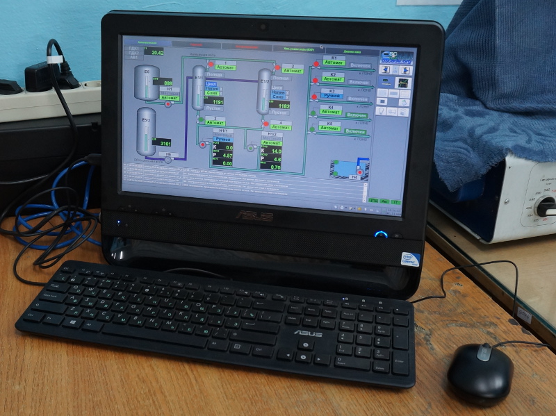
Рис. 4. АРМ САУ "Вода".
На АРМ встановлено системне ПЗ ALTLinux T6 та SCADA-система OpenSCADA 0.9-Work.
Виконано наступні заходи по загально-системній конфігурації:
- Налаштована синхронізація часу контролерів за АРМ.
- Створено обліковий запис оператору "operator".
- Налаштовано автоматичне завантаження робочого інтерфейсу від ім'я оператору та запуск системи OpenSCADA із проектом САУ.
- Оточення робочого стола TDE налаштовано для виключення зайвих функцій при роботі із діалоговими вікнами та виключення можливості закриття інтерфейсу оператора маніпулятором миші.
У процесі впровадження, перевірки та експлуатації OpenSCADA у ролі SCADA-станції було виявлено та виправлено низку проблем, а саме:
- Archive.FSArch: не підключення файлів архіву, джерело якого з'являється із затримкою.
- Archive.FSArch: викривлення деяких файлів архіву низької якості, за звичай хвилинні, супроводжуване втратою у кінці архіву недостовірності та як наслідок помилкового встановлення вершини архіву параметру далеко у майбутньому, на фізичному закінчені проблемного архівного файлу.
- UI.Vision: нестиковка градієнтного заповнення примітиву "ElFigure".
Інтерфейс користувача
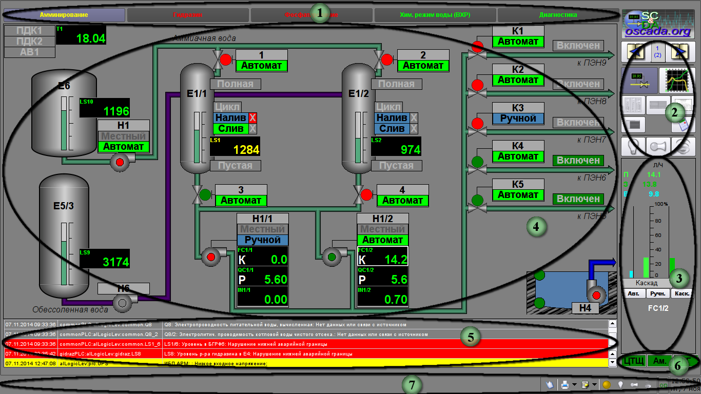
Інформація про технологічний процес відображається на відеокадрах, формованих програмою відображення на екрані дисплею, який входить до складу кожного АРМ. Відображувана інформація має визначену область виводу у межах відеокадру у залежності від його призначення. На рисунку 5 цифрами вказано області виводу відеокадру:
2. панель вибору типу відображення, навігації за відеокадрами та місцевої квітації;
3. панель управління;
4. робоча область відображення;
5. таблиця актуальних порушень;
6. стани підключень із ПЛК;
7. панель стану із інструментами.
Об'єкт управління розбивається функціонально та технологічно на блоки, звані об'єктами сигналізації. Кожному із об'єктів сигналізації ставиться у відповідність набір відеокадрів, об'єднаних у групи. Панель об'єктів сигналізації представляє собою набір екранних кнопок для вибору об'єктів та закріплених за ними груп відеокадрів.
Панель об'єктів сигналізації включає наступні кнопки:
- "Амінування" — вибір групи відеокадрів для управління та контролю Амінування живильної води.
- "Гідразин" — вибір групи відеокадрів для управління та контролю подачі Гідразин Гидратау у живильну воду.
- "Фосфатуванням" — вибір групи відеокадрів для управління та контролю подачі Фосфатів у котлову воду.
- "ВХР" — вибір групи відеокадрів для контролю хімічного режиму води.
- "Діагностика" — вибір групи відеокадрів діагностики обладнання автоматизації.
До кожного об'єкту сигналізації можуть бути прив'язані наступні типи відеокадрів:
- мнемосхеми;
- групи графіків;
- групи оглядових кадрів;
- групи контурів параметрів;
- документи.
Мнемосхеми
Вікно мнемосхеми викликається за натиском відповідної кнопки типу відображення і призначено для:
- графічного (мнемонічного) зображення фрагменту об'єкту управління;
- відображення поточного стану параметру у графічному вигляді;
- відображення поточного стану параметру у текстовому вигляді;
- виклику вікна управління параметром на панель управління.
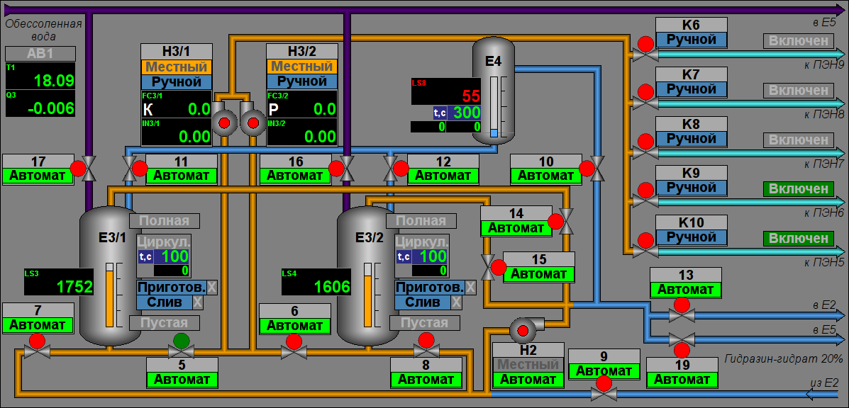
Амінування
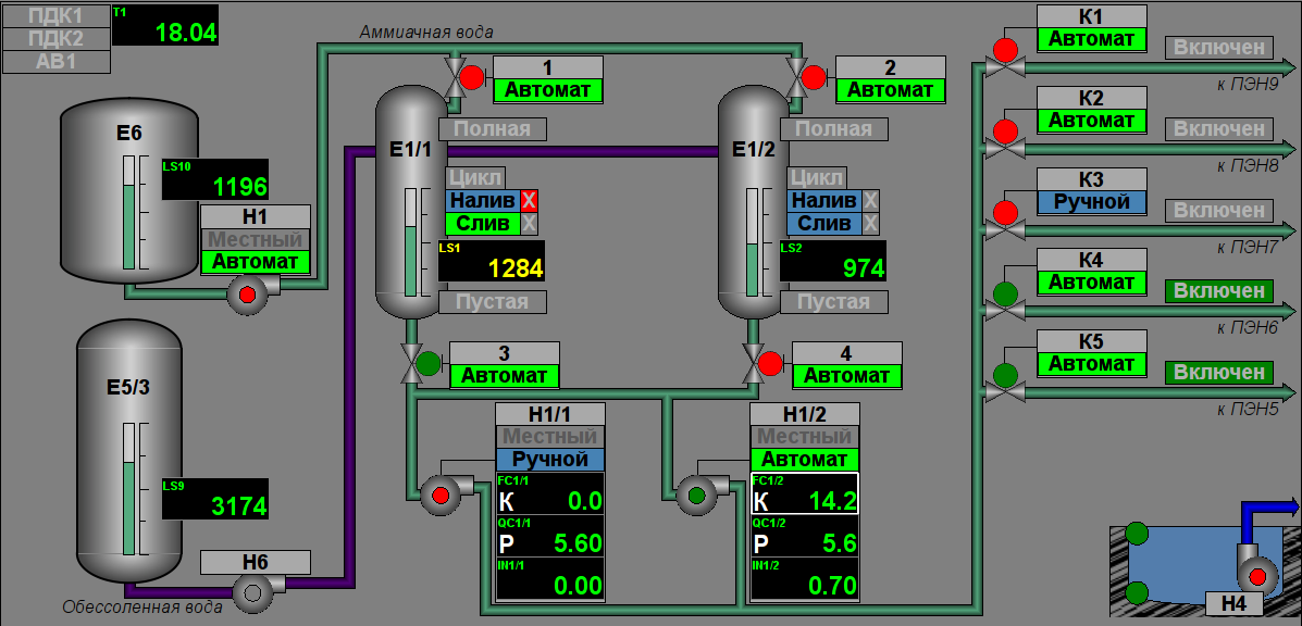
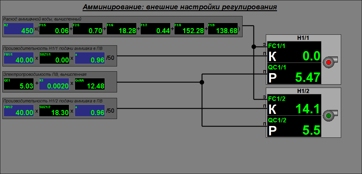
Управління процесом амінування здійснюється за посередництвом двох мнемосхем, де перша "Основна" (рис.6) містить мнемонічне зображення технологічного процесу з елементами контролю, а друга "Зовнішні налаштування регулювання" (рис. 7) містить зовнішні налаштування регулювання, відповідно.
Переклад
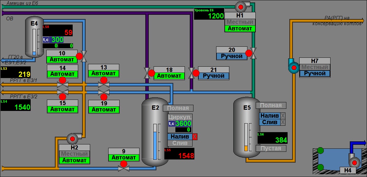
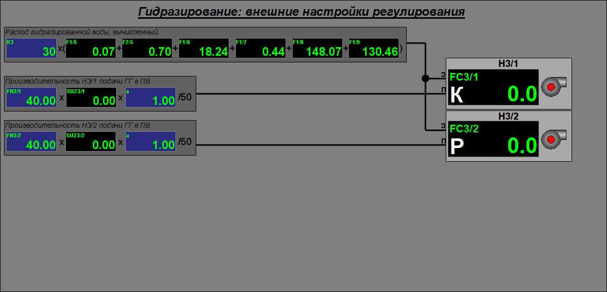
Гідразування
Управління процесом гідразування здійснюється за посередництвом трьох мнемосхем, де перші дві "Основні" (рис. 8 та 9) містять мнемонічне зображення технологічного процесу з елементами контролю, а третя "Зовнішні налаштування регулювання" (рис. 10) містить зовнішні налаштування регулювання, відповідно.
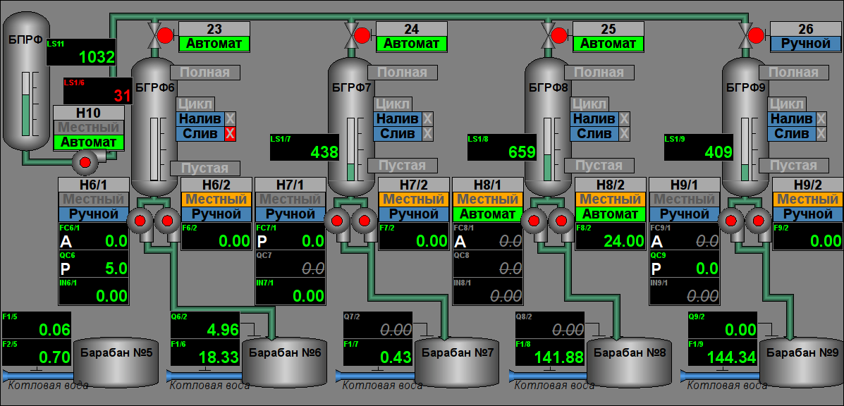
Фосфатування
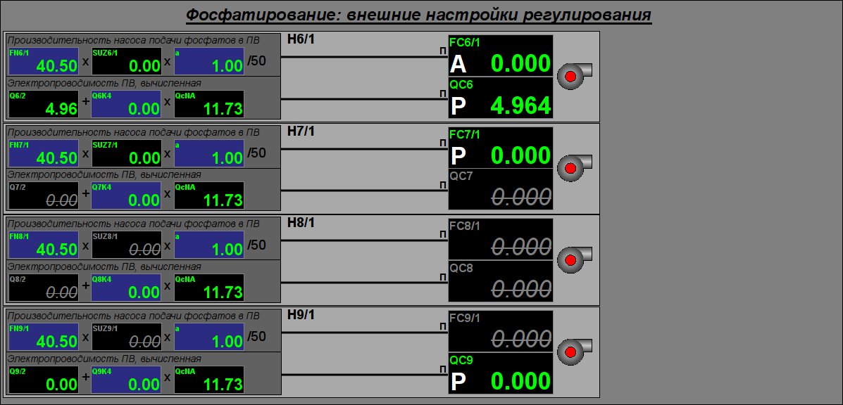
Управління процесом фосфатування здійснюється за посередництвом двох мнемосхем, де перша "Основна" (рис.11) містить мнемонічне зображення технологічного процесу з елементами контролю, а третя "Зовнішні налаштування регулювання" (рис.12) містить зовнішні налаштування регулювання, відповідно.
Хім. режим води (ВХР)
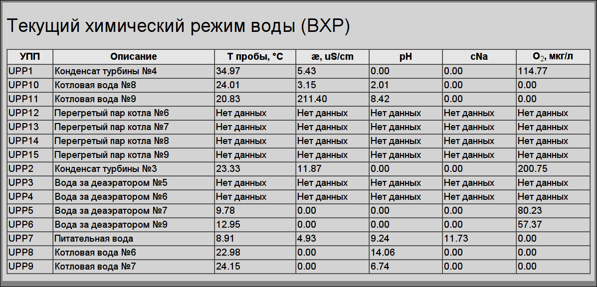
Контроль за хімічним режимом води здійснюється за посередництвом однієї мнемосхеми зі зведеною таблицею параметрів води (рис. 13).
Діагностика
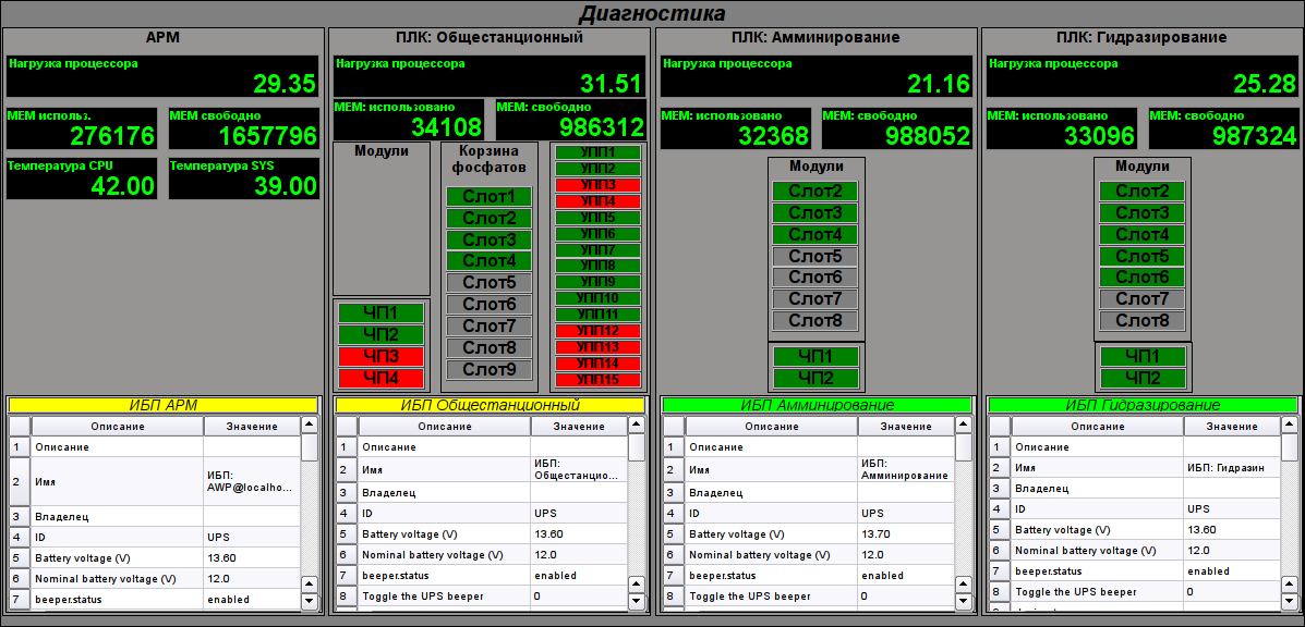
Контроль за обладнанням САУ здійснюється за посередництвом мнемосхеми "Основна" (рис. 14).
Неперервна продувка
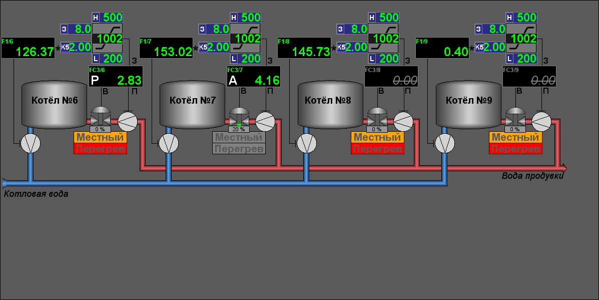
Управління процесом неперервної продувки здійснюється з АРМів "Млини" за посередництвом мнемосхеми "Основна" (рис.15).
Група графіків значень параметрів
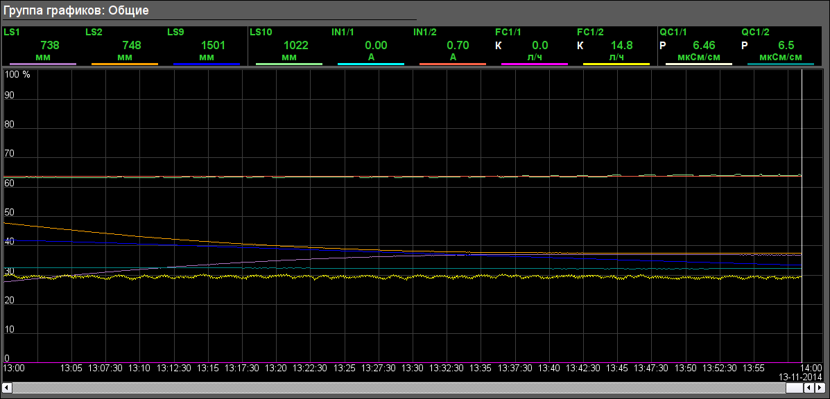
Вікно групи графіків викликається за натиском відповідної кнопки типу відображення та призначено для перегляду значень до десяти параметрів за визначений час у графічному вигляді.
Передбачено вісім груп графіків технічних параметрів у наступній конфігурації за об'єктами сигналізації:
- Амінування: "Загальні" (рис. 16)
- Гідразин: "Загальні", "Оточення"
- Фосфатування: "Рівні", "Продуктивність насосів", "Електропровідність", "Насоси", "Питома вода".
- Хім. режим води: "Питома вода", "Конденсат турбін", "Вода за деаераторами", "Котлова вода К6,7", "Котлова вода К8,9", "Перегрітий пар котла К6,7", "Перегрітий пар котла К8,9".
- Непер. продувка: "Витрати продувки", "Продувні клапани".
- Діагностика: "АРМ", "ПЛК: Загальностанційний", "ПЛК: Амінування", "ПЛК: Гідразування".
Документи
Вікно документів викликається за натиском кнопки типу відображення та містить документ з переліку доступних.
Журнал втручань
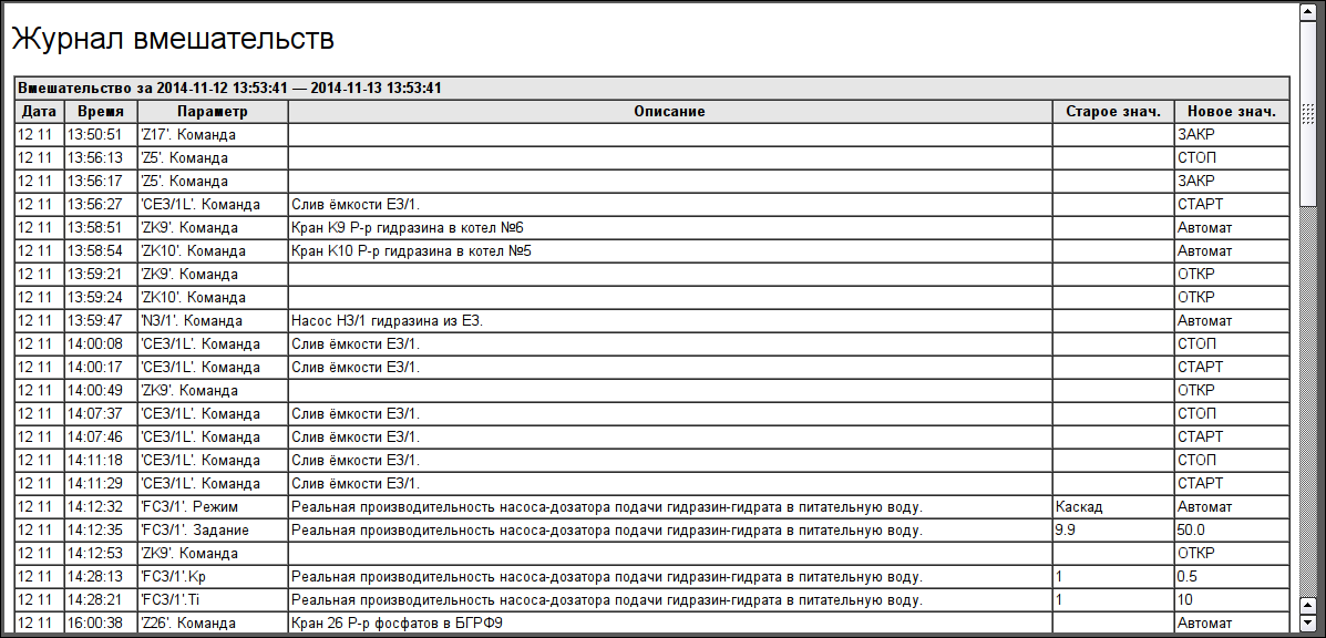
Журнал втручань (рис. 17) призначено для перегляду дій оператора, здійснюваних з даного АРМ (зміни стану ключів деблоку, режимів, коефіцієнтів налаштування регуляторів та інше).
Протокол порушень
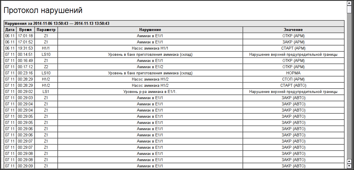
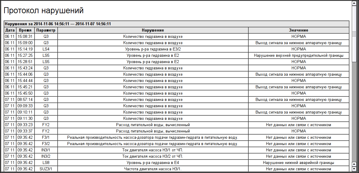
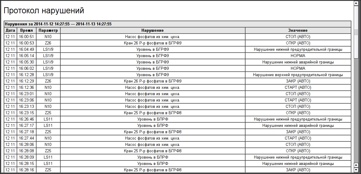
Протокол порушень (рис. 18, 19, 20) призначено для перегляду порушень за обраним об'єктом сигналізації (порушення параметром регламентних границь, недостовірність параметру, діагностика параметру та інше).
Посилання
