Regulation elements library
| Name: | regEl |
| Founded: | January 2010 |
| Version: | 1.0.0 |
| State: | Free (GPL) |
| Author: | Roman Savochenko |
| Description: | Regulation elements library. |
| Address: | DB in file: SQLite.LibDB.regEl ( |
About the library
Library is created to provide the functions of different control algorithms and can be used in programmable logic controllers (PLCs) based on OpenSCADA for construction control schemes. The library is not static, but based on the module JavaLikeCalc, allowing to create calculations on the Java-like language.
To address the functions of the library you can use static call address "DAQ.JavaLikeCalc.lib_regEl.{Func}()" or dynamic "SYS.DAQ.JavaLikeCalc["lib_regEl"]["{Func}"].call()", "SYS.DAQ.JavaLikeCalc["lib_regEl"].{Func}()". Where {Func} — function identifier in the library.
To connect the library to the project of the OpenSCADA station it is possible by downloading the attached file of the database, placing it in in the database directory of the station's project and creating the database object for the DB module "SQLite", indicating the database file in the configuration.
1 The library structure
In his part the library contains several functions often demanded by creating regulatory schemes. The functions' names and its parameters are available in three languages: English, Russian and Ukrainian.
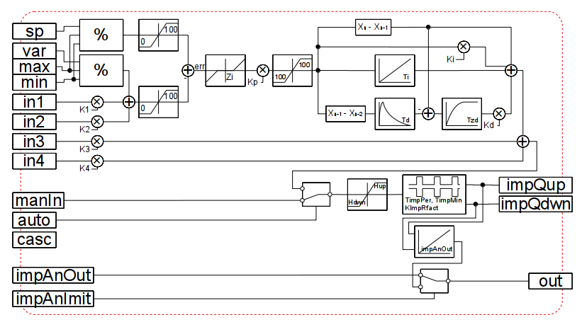
PID (unified) (pidUnif)
Description: Composite-unified analog and pulse PID. At the heart of the regulator is core a standard analog PID controller from the library "FLibComplex1" and the implementation of the PWM for the pulse part.
Parameters:
| ID | Parameter | Type | Mode | Hide | Default |
| var | Variable | Real | Input | false | 0 |
| sp | Setpoint | Real | Input | false | 0 |
| max | Scale: maximum | Real | Input | false | 100 |
| min | Scale: minimum | Real | Input | false | 0 |
| manIn | Manual input | Real | Input | false | 0 |
| out | Output (%) | Real | Return | false | 0 |
| impQup | Impulse output up | Boolean | Output | false | 0 |
| impQdwn | Impulse output down | Boolean | Output | false | 0 |
| analog | Analog | Boolean | Input | false | 1 |
| auto | Automate | Boolean | Input | false | 0 |
| casc | Cascade | Boolean | Input | false | 0 |
| Kp | Gain | Real | Input | false | 1 |
| Ti | Ti (ms) | Integer | Input | false | 1000 |
| Kd | Gain differential | Real | Input | false | 1 |
| Td | Td (ms) | Integer | Input | false | 0 |
| Tzd | T differential lag (ms) | Integer | Input | false | 0 |
| TImpPer | T impulses period (ms) | Integer | Input | false | 5000 |
| TImpMin | T minimal impulse (ms) | Integer | Input | false | 500 |
| KImpRfact | Impulse rate factor | Real | Input | false | 1 |
| Hup | Upper output border (%) | Real | Input | false | 100 |
| Hdwn | Neither output border (%) | Real | Input | false | 0 |
| Zi | Insensitivity (%) | Real | Input | false | 0 |
| followSp | Follow to variable by setpoint into manual | Boolean | Input | false | 1 |
| K1 | Coefficient of input 1 | Real | Input | false | 0 |
| in1 | Input 1 | Real | Input | false | 0 |
| K2 | Coefficient of input 2 | Real | Input | false | 0 |
| in2 | Input 2 | Real | Input | false | 0 |
| K3 | Coefficient of input 3 | Real | Input | false | 0 |
| in3 | Input 3 | Real | Input | false | 0 |
| K4 | Coefficient of input 4 | Real | Input | false | 0 |
| in4 | Input 4 | Real | Input | false | 0 |
| impAnOut | Analog position of impulse regulator | Real | Input | false | 0 |
| impAnImit | Analog position imitation | Boolean | Input | false | 0 |
| impQupTm | Imp. output up lag for GUI | Integer | Output | false | 0 |
| impQdwnTm | Imp. output down lag for GUI | Integer | Output | false | 0 |
| f_frq | Calc frequency (Hz) | Integer | Input | true | 1 |
| f_start | First start | Boolean | Input | true | 0 |
| f_stop | Last start | Boolean | Input | true | 0 |
| int | Integral accumulation | Real | Output | true | 0 |
| dif | Differential accumulation | Real | Output | true | 0 |
| lag | Lag accumulation | Real | Output | true | 0 |
| impLag | Impulse lag time | Real | Output | true | 0 |
| perLag | New impulse generation time | Real | Output | true | 0 |
Structure:
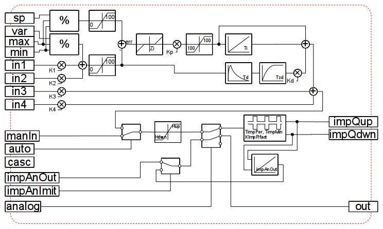
PID dynamic (pidUnifD)
Description: Completely identical to unified PID regulator is implemented dynamically on JavaLikeCalc. The dynamic implementation allows you to easily adapt the regulator to the desired requirements, simply by editing it.
Parameters:
| ID | Parameter | Type | Mode | Hide | Default |
| var | Variable | Real | Input | false | 0 |
| sp | Setpoint | Real | Input | false | 0 |
| max | Scale: maximum | Real | Input | false | 100 |
| min | Scale: minimum | Real | Input | false | 0 |
| manIn | Manual input | Real | Input | false | 0 |
| out | Output (%) | Real | Return | false | 0 |
| impQup | Impulse output up | Boolean | Output | false | 0 |
| impQdwn | Impulse output down | Boolean | Output | false | 0 |
| analog | Analog | Boolean | Input | false | 1 |
| auto | Automate | Boolean | Input | false | 0 |
| casc | Cascade | Boolean | Input | false | 0 |
| Kp | Gain | Real | Input | false | 1 |
| Ti | Ti (ms) | Integer | Input | false | 1000 |
| Kd | Gain differential | Real | Input | false | 1 |
| Td | Td (ms) | Integer | Input | false | 0 |
| Tzd | T differential lag (ms) | Integer | Input | false | 0 |
| TImpPer | T impulses period (ms) | Integer | Input | false | 5000 |
| TImpMin | T minimal impulse (ms) | Integer | Input | false | 500 |
| KImpRfact | Impulse rate factor | Real | Input | false | 1 |
| Hup | Upper output border (%) | Real | Input | false | 100 |
| Hdwn | Neither output border (%) | Real | Input | false | 0 |
| Zi | Insensitivity (%) | Real | Input | false | 0 |
| followSp | Follow to variable by setpoint into manual | Boolean | Input | false | 1 |
| K1 | Coefficient of input 1 | Real | Input | false | 0 |
| in1 | Input 1 | Real | Input | false | 0 |
| K2 | Coefficient of input 2 | Real | Input | false | 0 |
| in2 | Input 2 | Real | Input | false | 0 |
| K3 | Coefficient of input 3 | Real | Input | false | 0 |
| in3 | Input 3 | Real | Input | false | 0 |
| K4 | Coefficient of input 4 | Real | Input | false | 0 |
| in4 | Input 4 | Real | Input | false | 0 |
| QO | Opened state of the control mechanism | Boolean | Input | false | 0 |
| QZ | Closed state of the control mechanism | Boolean | Input | false | 0 |
| impAnOut | Real analog position of impulse regulator, [0...100], -1 - disable | Real | Input | false | 0 |
| impAnImit | Full stroke time for analog position imitation, s | Boolean | Input | false | 0 |
| impQupTm | Imp. output up lag for GUI | Integer | Output | false | 0 |
| impQdwnTm | Imp. output down lag for GUI | Integer | Output | false | 0 |
| f_frq | Calc frequency (Hz) | Integer | Input | true | 1 |
| f_start | First start | Boolean | Input | true | 0 |
| f_stop | Last start | Boolean | Input | true | 0 |
| impLag | Impulse lag time | Real | Output | true | 0 |
| perLag | New impulse generation time | Real | Output | true | 0 |
| integ | Integral accumulation | Real | Output | true | 0 |
| difer | Differential accumulation | Real | Output | true | 0 |
| dlag | Differential lag accumulation | Real | Output | true | 0 |
Structure:
PID pulse (pidImp)
Description: Specialized pulse PID regulator is implemented on a special algorithm with compensation of double integration.
Parameters:
| ID | Parameter | Type | Mode | Hide | Default |
| var | Variable | Real | Input | false | 0 |
| sp | Setpoint | Real | Input | false | 0 |
| max | Scale: maximum | Real | Input | false | 100 |
| min | Scale: minimum | Real | Input | false | 0 |
| manIn | Manual input | Real | Input | false | 0 |
| out | Output (%) | Real | Return | false | 0 |
| outPID | PID output | Real | Output | false | 0 |
| impQup | Impulse output up | Boolean | Output | false | 0 |
| impQdwn | Impulse output down | Boolean | Output | false | 0 |
| auto | Automate | Boolean | Input | false | 0 |
| casc | Cascade | Boolean | Input | false | 0 |
| Kp | Gain | Real | Input | false | 1 |
| Ki | Gain integer | Real | Input | false | 1 |
| Ti | Ti (ms) | Integer | Input | false | 1000 |
| Kd | Gain differential | Real | Input | false | 1 |
| Td | Td (ms) | Integer | Input | false | 0 |
| Tzd | T differential lag (ms) | Integer | Input | false | 0 |
| TImpPer | T impulses period (ms) | Integer | Input | false | 5000 |
| TImpMin | T minimal impulse (ms) | Integer | Input | false | 500 |
| KImpRfact | Impulse rate factor | Real | Input | false | 1 |
| Hup | Upper output border (%) | Real | Input | false | 100 |
| Hdwn | Neither output border (%) | Real | Input | false | 0 |
| Zi | Insensitivity (%) | Real | Input | false | 0 |
| followSp | Follow to variable by setpoint into manual | Boolean | Input | false | 1 |
| K1 | Coefficient of input 1 | Real | Input | false | 0 |
| in1 | Input 1 | Real | Input | false | 0 |
| K2 | Coefficient of input 2 | Real | Input | false | 0 |
| in2 | Input 2 | Real | Input | false | 0 |
| K3 | Coefficient of input 3 | Real | Input | false | 0 |
| in3 | Input 3 | Real | Input | false | 0 |
| K4 | Coefficient of input 4 | Real | Input | false | 0 |
| in4 | Input 4 | Real | Input | false | 0 |
| impAnOut | Analog position of impulse regulator | Real | Input | false | 0 |
| impAnImit | Analog position imitation | Boolean | Input | false | 0 |
| impQupTm | Imp. output up lag for GUI | Integer | Output | false | 0 |
| impQdwnTm | Imp. output down lag for GUI | Integer | Output | false | 0 |
| f_frq | Calc frequency (Hz) | Integer | Input | true | 1 |
| f_start | First start | Boolean | Input | true | 0 |
| f_stop | Last start | Boolean | Input | true | 0 |
| impLag | Impulse lag time | Real | Output | true | 0 |
| perLag | New impulse generation time | Real | Output | true | 0 |
| integ | Integral accumulation | Real | Output | true | 0 |
| difer | Differential accumulation | Real | Output | true | 0 |
| dlag | Differential lag accumulation | Real | Output | true | 0 |
| err1 | Error step back | Real | Output | true | 0 |
| err2 | Error two step back | Real | Output | true | 0 |
Structure: